
- Home
- Getting Started
- Documentation
- Release Notes
- Tour the Interface
- Tour the Layers
- JMARS Video Tutorials
- Lat/Lon Grid Layer
- Map Scalebar
- Nomenclature
- Crater Counting
- 3D
- Shape Layer
- Mosaics
- Map
- Advanced/Custom Maps
- Graphic/Numeric Maps
- Custom Map Sharing
- Stamp
- THEMIS
- MOC
- Viking
- CRISM Stamp Layer
- CTX
- HiRise
- HiRISE Anaglyph
- HiRISE DTM
- HRSC
- OMEGA
- Region of Interest
- TES
- THEMIS Planning
- Investigate Layer
- Landing Site Layer
- Tutorials
- Video Tutorials
- Displaying the Main View in 3D
- Finding THEMIS Observation Opportunities
- Submitting a THEMIS Region of Interest
- Loading a Custom Map
- Viewing TES Data in JMARS
- Using the Shape Layer
- Shape Layer: Intersect, Merge, and Subtract polygons from each other
- Shape Layer: Ellipse Drawing
- Shape Layer: Selecting a non-default column for circle-radius
- Shape Layer: Selecting a non-default column for fill-color
- Shape Layer: Add a Map Sampling Column
- Shape Layer: Adding a new color column based on the values of a radius column
- Shape Layer: Using Expressions
- Using JMARS for MSIP
- Introduction to SHARAD Radargrams
- Creating Numeric Maps
- Proxy/Firewall
- JMARS Shortcut Keys
- JMARS Data Submission
- FAQ
- Open Source
- References
- Social Media
- Podcasts/Demos
- Download JMARS
Visible and Infrared Mineralogical Mapping Spectrometer (OMEGA) Stamp Layer
The OMEGA Stamp Layer will display stamps for all observations acquired by the Visible and Infrared Mineralogical Mapping Spectrometer (OMEGA) aboard the European Space Agency's Mars Express orbiter. While the search interface is similar to the THEMIS Stamp Layer, there are some differences that allow users to search for observations based on the unique parameters associated with OMEGA observations.
Open the OMEGA Stamp Layer
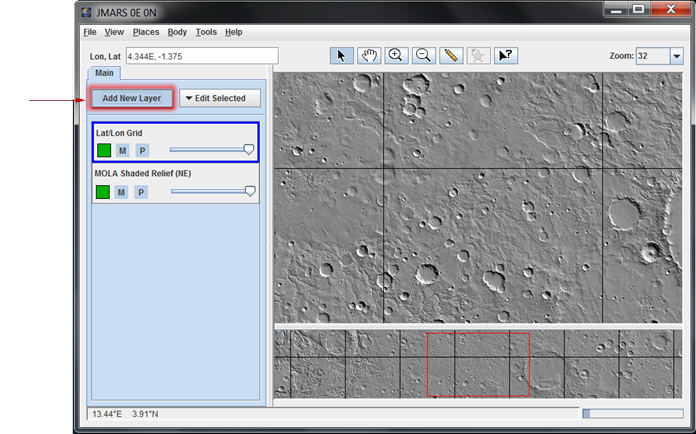
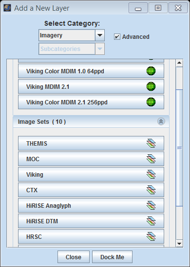
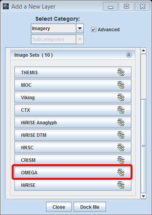
- Open the Stamp Layer: Chose "Add New Layer" -> "Imagery" -> "OMEGA" OR "Add New Layer" -> "Instrument" -> "OMEGA".
- Search Parameter Categories: The search parameters are divided into categories since there are so many of them. Clicking on the down arrow on the right side of the category name will reveal all the search parameters in that category. The categories are:
- Basic Parameters
- Advanced Parameters
- Enter Search Parameters: It is not necessary to enter values for each parameter, but the more specific your search the faster it will be. The allowable values for each field are given in the quick reference table below followed by more detailed descriptions of each search parameter.
- Perform Image Search: Clicking OK will make the Stamp Layer perform the search and display the results. Depending on how specific the search parameters are, it may take the Stamp Layer a few minutes to find and create stamps for all of the images. Once the stamps are displayed in the Viewing Window, users can right-click on an outline to view the image in a web browser. A rendering option is not currently available for OMEGA data.

OMEGA Search Parameter Glossary
|
Filter Type |
Acceptable Values |
Description |
|
Image ID(s) |
Any Specific Image ID Number(s) |
A unique identifier for each observation commanded; follows the pattern ORBnnnn_x, where:
|
|
Min/Max Longitude |
0 to 360(East Longitude = Positive) |
This is the approximate longitude on the planet Mars of the image center. All values are based on the IAU 2000 aerocentric model of Mars with east positive longitude. |
|
Min/Max Latitude |
90 to -90(North Latitude = Positive) |
This is the approximate latitude on the planet Mars of the image center. All values are based on the IAU 2000 aerocentric model of Mars with north positive latitude. |
|
Min/Max Orbit |
0 - 4900 |
The MEX orbit during which the observation was acquired. |
|
Pointing Mode |
NADIR |
The spacecraft pointing mode at the time of the observation. |
|
Min/Max Solar Longitude |
0 - 360(Northern Vernal Equinox = 0) |
This is the position of Mars relative to the Sun measured in degrees from the vernal equinox (start of northern Spring). This number is used as a measure of Martian seasons. (Also known as heliocentric longitude and abbreviated Ls.)
|
|
Min/Max Phase Angle |
0 - 180 - (0 = OMEGA and Sun In-Line) |
This is the angle between the sun, the surface, and the MOC at the time the picture was obtained. |
|
Min/Max Solar Incidence Angle |
0 - 180(Sun Directly Overhead = 0) |
Derived for the center of the image, this is the angle between the Sun and a "normal" drawn perpendicular to the planet's surface at the time the image was acquired. A higher incidence angle means that a person standing on the ground would see the sun lower toward the horizon. |
|
Min/Max Emission Angle |
0 - 180(0=OMEGA Directly Overhead) |
Measured from the center of the image, this is the angle between the MOC and a "normal" drawn perpendicular to the planet's surface. In most cases, the MOC is looking "straight down" and the emission angle is thus close to 0°. |
|
Min/Max Slant Distance |
250 - 21,000(Distance from sub-MEX point to image center, in meters) |
This number is similar to the spacecraft altitude, but also takes into account the emission angle. If the emission angle is 0 then this number is the same as the spacecraft altitude. If the emission angle is much greater than 0, then the "slant distance" to the surface at the center of the image is also greater than the spacecraft altitude. |
|
Min/Max Spacecraft Altitude |
270 - 20,000 (in km) |
The distance from the spacecraft to the surface of the reference body, measured along a line normal to the surface, |
|
Local True Solar Time (24hr) |
00:00 - 24:00(Given as HH:MM in Mars Time) |
This is the local time on Mars at the center of the image relative to a division of the martian day into 24 equal parts. A martian day is slightly longer than 24 hours and 37 minutes long. |
|
Min/Max Horizontal Pixel Scale |
330 - 25,100(in meters/pixel) |
The horizontal resolution, in meters/pixel, at the center pixel of the observation. |
|
Min/Max Vertical Pixel Scale |
330 - 1,000,000(in meters/pixel) |
The vertical resolution, in meter/pixel, at the center pixel of the observation. |


Stamp Layer Functions
The CRISM Stamp Layer's functions are identical to the functions of the Stamp Layer and are explained in detail on the Stamp Layer page.