
- Home
- Getting Started
- Documentation
- Release Notes
- Tour the Interface
- Tour the Layers
- JMARS Video Tutorials
- Lat/Lon Grid Layer
- Map Scalebar
- Nomenclature
- Crater Counting
- 3D
- Shape Layer
- Mosaics
- Map
- Advanced/Custom Maps
- Graphic/Numeric Maps
- Custom Map Sharing
- Stamp
- THEMIS
- MOC
- Viking
- CRISM Stamp Layer
- CTX
- HiRise
- HiRISE Anaglyph
- HiRISE DTM
- HRSC
- OMEGA
- Region of Interest
- TES
- THEMIS Planning
- Investigate Layer
- Landing Site Layer
- Tutorials
- Video Tutorials
- Displaying the Main View in 3D
- Finding THEMIS Observation Opportunities
- Submitting a THEMIS Region of Interest
- Loading a Custom Map
- Viewing TES Data in JMARS
- Using the Shape Layer
- Shape Layer: Intersect, Merge, and Subtract polygons from each other
- Shape Layer: Ellipse Drawing
- Shape Layer: Selecting a non-default column for circle-radius
- Shape Layer: Selecting a non-default column for fill-color
- Shape Layer: Add a Map Sampling Column
- Shape Layer: Adding a new color column based on the values of a radius column
- Shape Layer: Using Expressions
- Using JMARS for MSIP
- Introduction to SHARAD Radargrams
- Creating Numeric Maps
- Proxy/Firewall
- JMARS Shortcut Keys
- JMARS Data Submission
- FAQ
- Open Source
- References
- Social Media
- Podcasts/Demos
- Download JMARS
Delivery 0
Delivery 0
Create JMARS Account
Step 1
Go to the JMARS website: https://jmars.mars.asu.edu/
Step 2
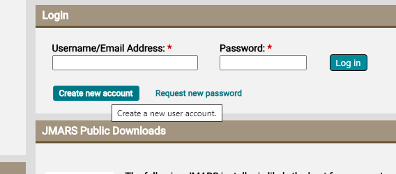
Create new user account by clicking “Create new account” (Make sure to use the same email address that will be used in other Clipper tools) :
Step 3
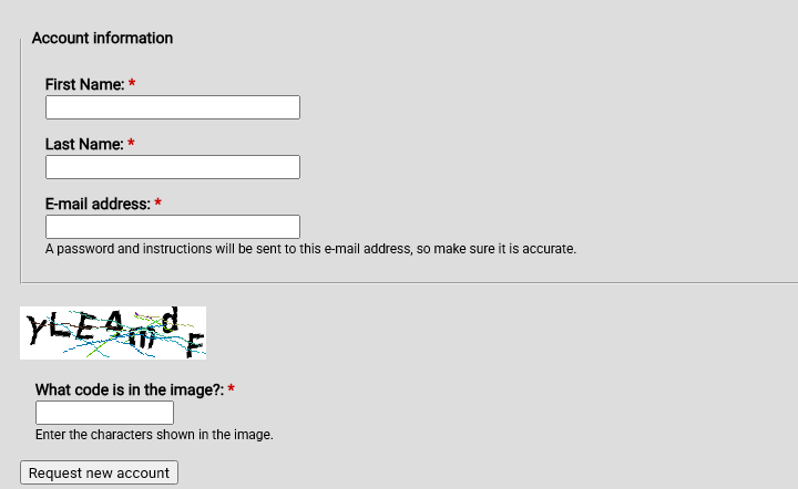
Use the form to request a new account:
Step 4
Once you have established your JMARS account, send your account email to your contact person from JPL so that they can request JMARS Europa Clipper Team access for your new account. Once that information is forwarded to the JMARS team, they will update account access and send an email notification when it is done (usually within one business day).
Step 5
Once you have received notification of access, return to the JMARS homepage: https://jmars.mars.asu.edu/
Step 6
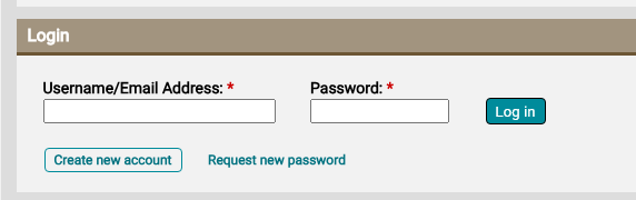
Log in to the JMARS website:
Step 7
You should see the Europa Clipper Team Downloads section on the right side of the page:

Step 8
Use the link in that section to download and execute the installer for your system. In most cases, the default values should be fine.
Step 9
Run JMARS and continue to the next section for further instructions.
Using the Clipper Pointing Validation Layer
Step 1
Start JMARS. The JMARS login window (Figure 1) will appear:
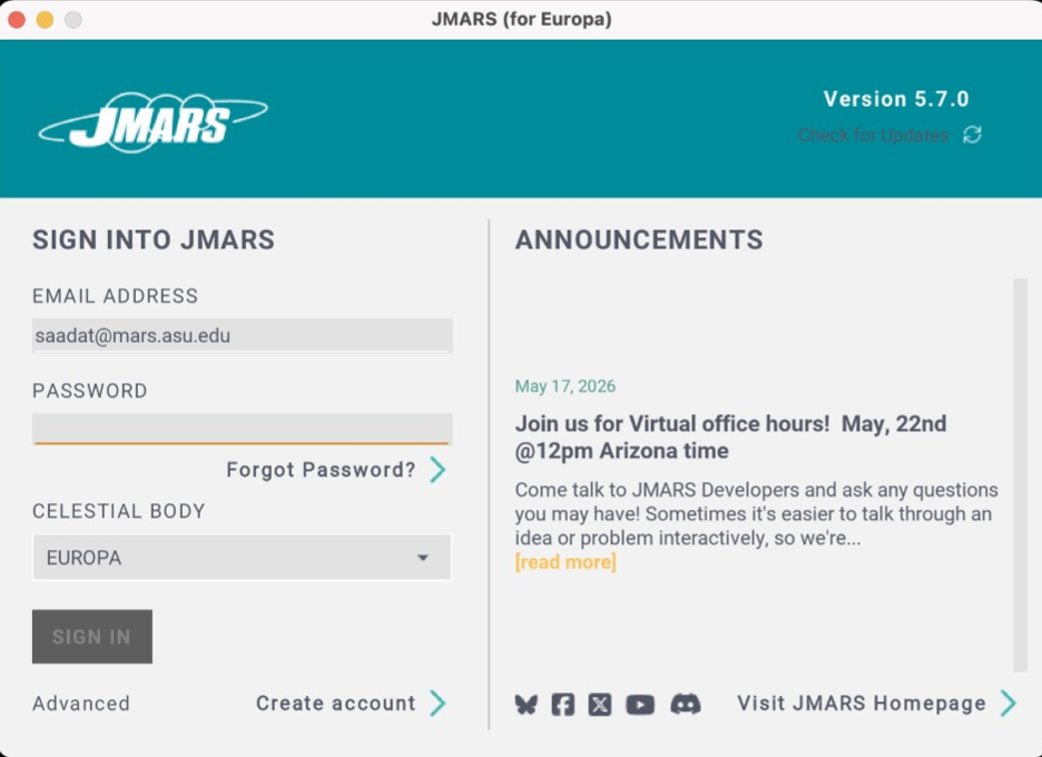
Figure 1: JMARS Login Window
Step 2
Type in your login credentials and select the body you will be working with (Earth in this case) as shown below (Figure 2). Then press the “SIGN IN” button.
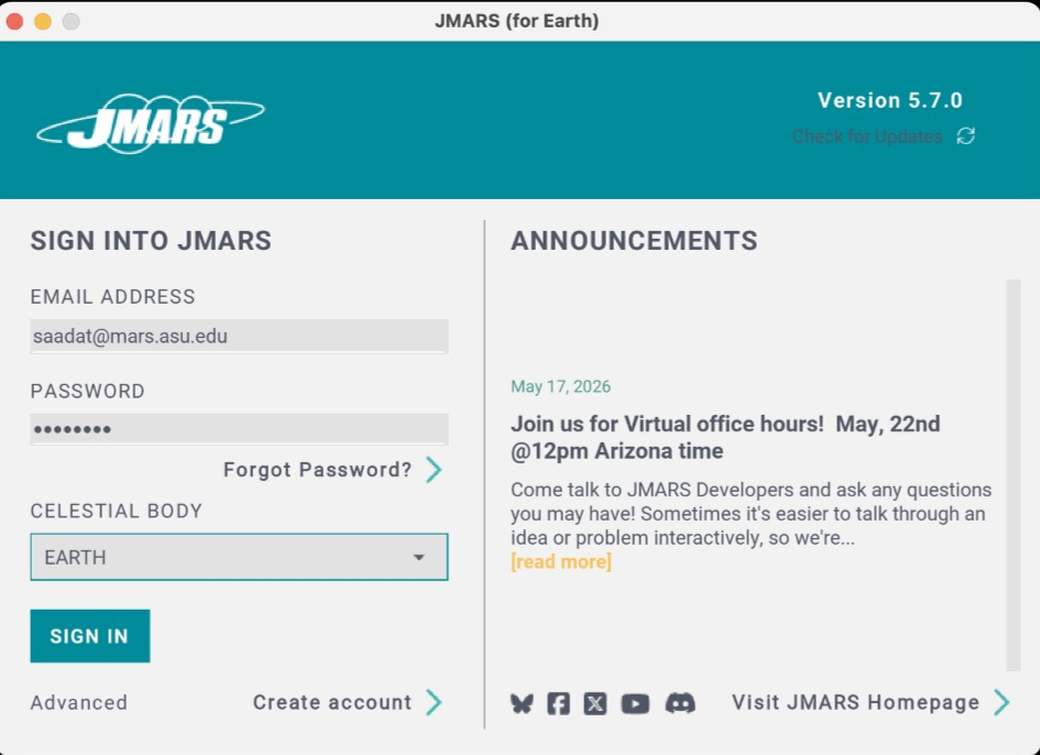
Figure 2: JMARS login window with credentials entered and body selected
Step 3
JMARS main window (Figure 3) will appear.
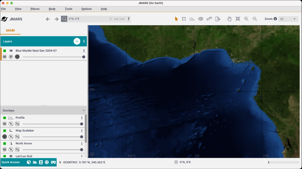
Figure 3: JMARS main window
Step 4
Press the “+” button to open the “Add New Layer” dialog. Then type “Clipper” in the search box (Figure 4).
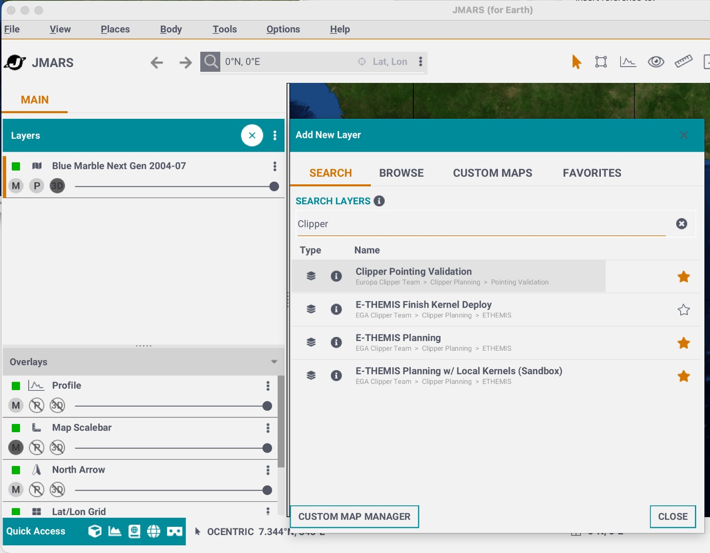
Figure 4: Add New Layer dialog with "Clipper" typed in the "SEARCH LAYERS" box
Step 5
Click on the “Clipper Pointing Validation” choice in the search results to start the “Clipper Pointing Validation” layer. JMARS will show the layer startup dialog ().
Step 6
Select the appropriate kernel set (for Earth use “earth_latest”). Update the start and end times to a narrower range (Figure 5) and press “Continue”.
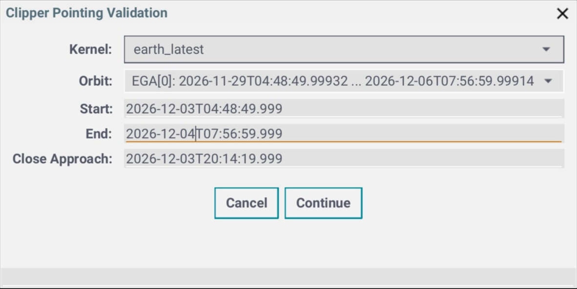
Figure 5: Clipper Pointing Validation Layer startup dialog with Start and End times updated to a section around the closest approach
Step 7
A “Pointing Validation Layer” will be added to the Layer Manager at the left of the JMARS main window (Figure 6) and a 3D window will open. Some status dialogs may appear in the process.
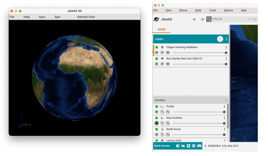
Figure 6: JMARS Layer Manager showing the "Clipper Pointing Validation" layer as the top-most layer in the stacking order (right) and 3D window (left).
Step 8
Double-click on the “Clipper Pointing Validation” layer in the layer manager to open its focus panel (Figure 7).
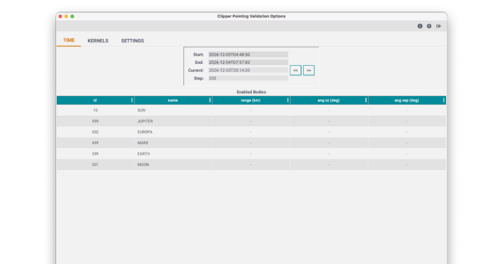
Figure 7: Clipper Pointing Validation layer focus panel
Step 9
Press the Enter key in the “Current” time box or the use the “<<” or “>>” keys to change current time. The table towards the bottom will be updated with values and after a few seconds the 3D view will show the orbit track, spacecraft and any selected bodies (Figure 8).
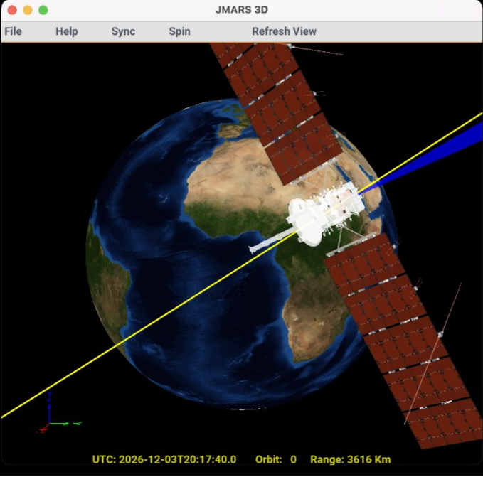
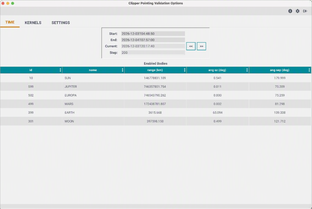
Figure 8: Focus Panel "TIME" tab showing updated table (right) and updated 3D view (left)
Step 10
Press and hold either the “<<” or “>>” button to move backwards or forwards in time. The 3D view will update to show the updated position and orientation of the spacecraft. The 3D view will also show the updated position of any other bodies currently enabled.
Step 11
Switch to the “SETTINGS” panel of the focus panel (Figure 9) to see the various settings, including color choices, line widths, field-of-views to display and whether the field-of-view should be displayed as cones / frustums. It also allows one to scale the spacecraft model currently being displayed, enable the display of other bodies and their labels etc.
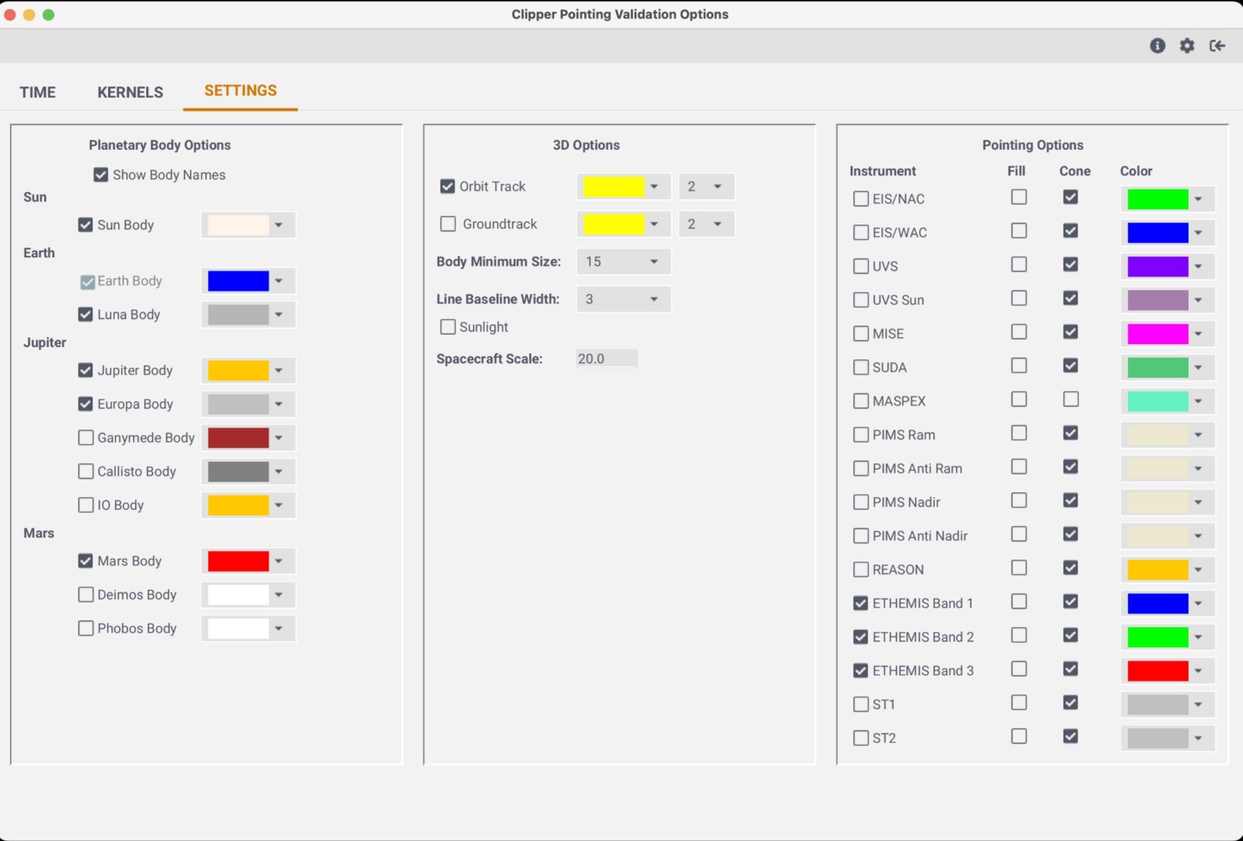
Figure 9: Pointing Validation Layer's focus panel showing the settings tab
Step 12
Zoom out in the 3D window and enable other field-of-views to see the resulting view in 3D. Then, switch back to the “TIME” tab to move backwards or forwards in time.
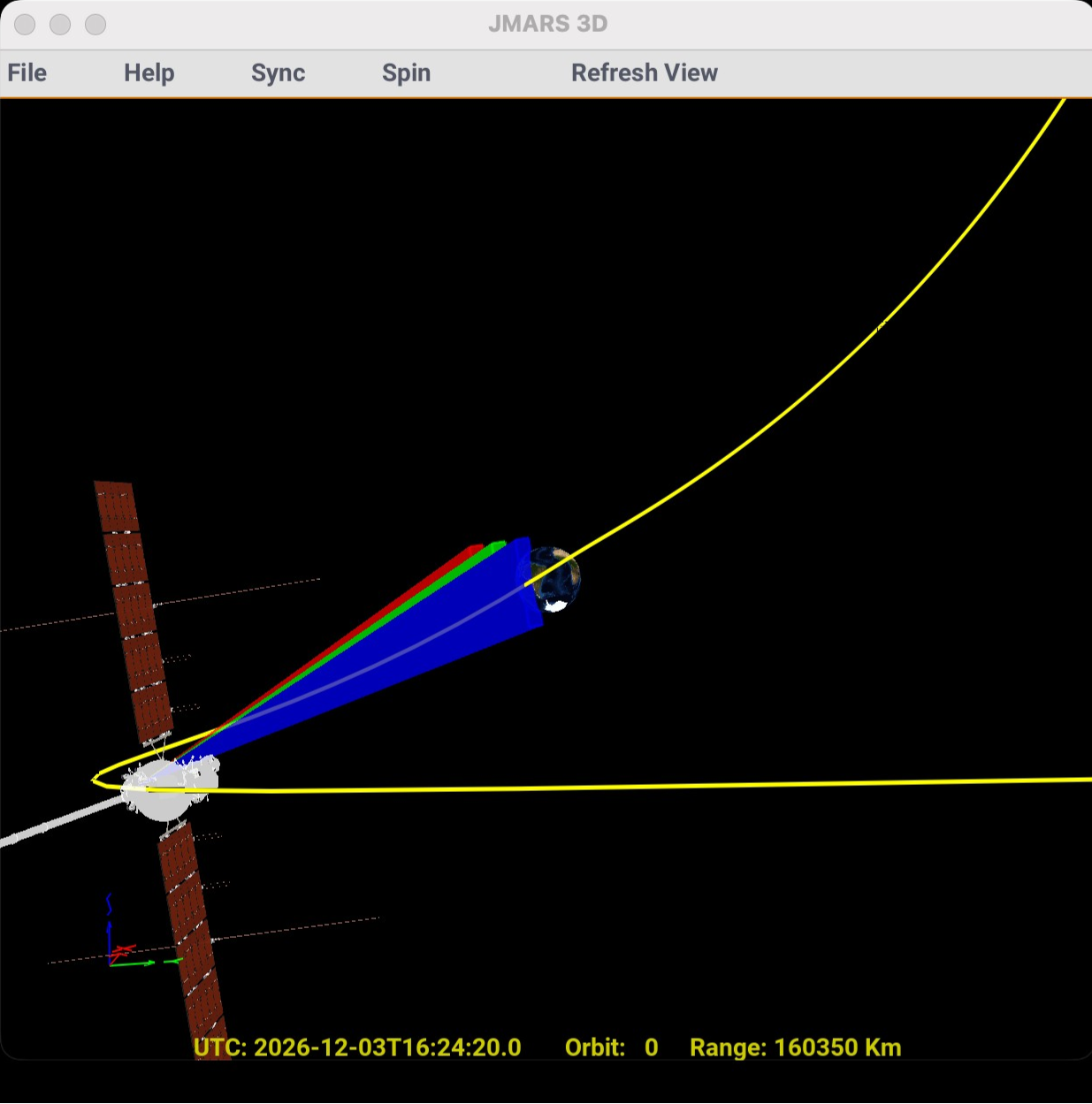
Figure 10: Updated 3D view showing the Clipper spacecraft imaging the Earth. E-THEMIS bands are being displayed as condes.
Step 13
The “KERNELS” tab shows the current set of loaded kernels (Figure 11).
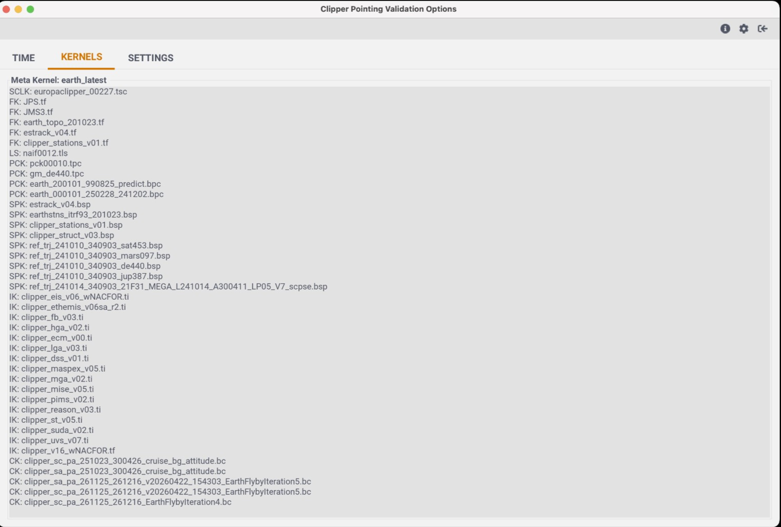
Figure 11: Pointing Validation Layer's focus panel showing the Kernels tab
Step 14
To close the layer, use the “Exit” option in the “File” menu of the main view ().
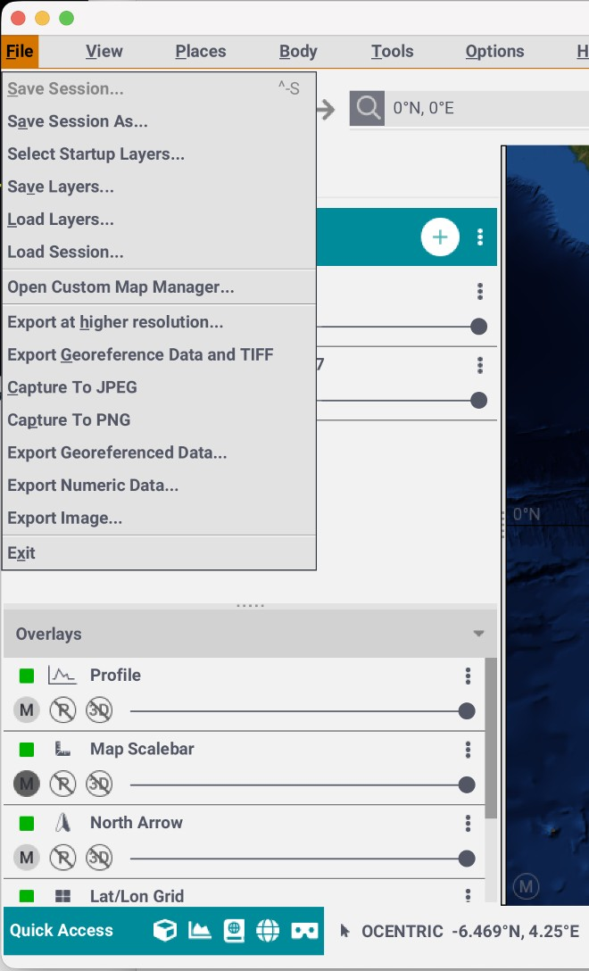
Figure 12: Main View showing File menu