
- Home
- Getting Started
- Documentation
- Release Notes
- Tour the Interface
- Tour the Layers
- JMARS Video Tutorials
- Lat/Lon Grid Layer
- Map Scalebar
- Nomenclature
- Crater Counting
- 3D
- Shape Layer
- Mosaics
- Map
- Advanced/Custom Maps
- Graphic/Numeric Maps
- Custom Map Sharing
- Stamp
- THEMIS
- MOC
- Viking
- CRISM Stamp Layer
- CTX
- HiRise
- HiRISE Anaglyph
- HiRISE DTM
- HRSC
- OMEGA
- Region of Interest
- TES
- THEMIS Planning
- Investigate Layer
- Landing Site Layer
- Tutorials
- Video Tutorials
- Displaying the Main View in 3D
- Finding THEMIS Observation Opportunities
- Submitting a THEMIS Region of Interest
- Loading a Custom Map
- Viewing TES Data in JMARS
- Using the Shape Layer
- Shape Layer: Intersect, Merge, and Subtract polygons from each other
- Shape Layer: Ellipse Drawing
- Shape Layer: Selecting a non-default column for circle-radius
- Shape Layer: Selecting a non-default column for fill-color
- Shape Layer: Add a Map Sampling Column
- Shape Layer: Adding a new color column based on the values of a radius column
- Shape Layer: Using Expressions
- Using JMARS for MSIP
- Introduction to SHARAD Radargrams
- Creating Numeric Maps
- Proxy/Firewall
- JMARS Shortcut Keys
- JMARS Data Submission
- FAQ
- Open Source
- References
- Social Media
- Podcasts/Demos
- Download JMARS
Thermal Emission Imaging System (THEMIS) Stamp Layer
The THEMIS Stamp Layer will display outlines (or "stamps") for all VIS and IR observations acquired by the Thermal Emission Imaging System (THEMIS) camera onboard Mars Odyssey. Since the THEMIS dataset is so large, there are numerous search parameters that allow users to retrieve stamps for only the observations they are interested in viewing.

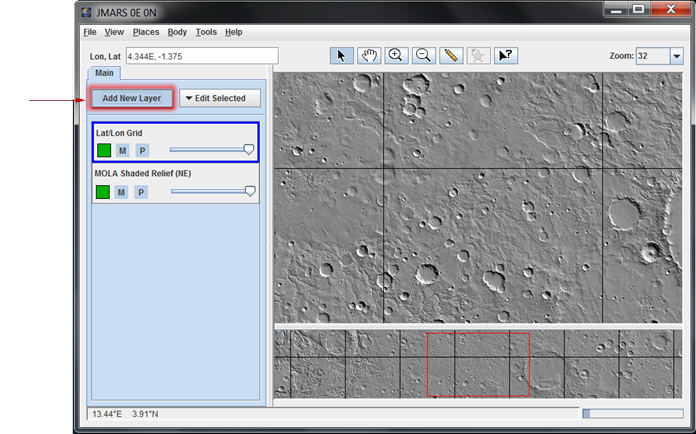
Open the THEMIS Stamp Layer
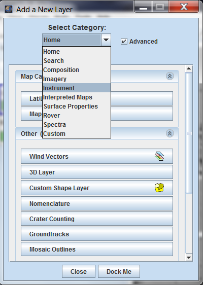
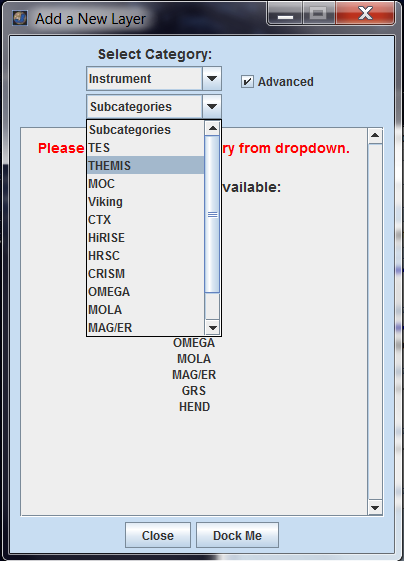
- Open the Stamp Layer: In the Layer Manager chose "Add New Layer" -> "Stamps" -> "THEMIS Stamps".
- Search Parameter Categories: The search parameters are divided into categories since there are so many of them. Clicking on the down arrow on the right side of the category name will reveal all the search parameters in that category. The categories are:
- Image Location Parameters
- Viewing Conditions Parameters
- Observation Parameters
- IR Derived Science Parameters
- Quality Parameters
- Publication Parameters
NOTE: A search can be performed with parameters set in multiple categories.
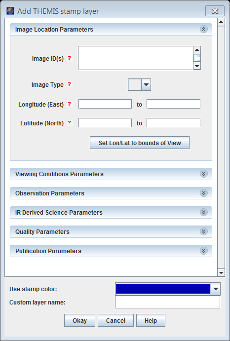
- Enter Search Parameters: It is not necessary to enter values for all parameters, but the more specific your search the faster it will be. The allowable values for each field are given in the quick reference table below.
- Perform Image Search: Clicking OK will make the Stamp Layer perform the search and display the results. Depending on how specific the search parameters are, it may take the Stamp Layer a few minutes to find and create stamps for all of the images. Once the stamps are displayed in the Viewing Window, users can right-click on an outline to either render the image (display the image data in JMARS) or view the image in a web browser.


THEMIS Search Parameter Glossary
|
Filter Type |
Acceptable Values |
Description |
|
Image ID(s) |
Any Specific Image ID Number(s) |
A unique identifier for each observation commanded; follows the pattern Xoooooiii, where:
|
|
Image Type |
VIS- Visible Observations IR- Infrared Observations Blank- Any Observation Type |
The type of the image i.e. Visible (VIS) or Infrared (IR). |
|
Min/Max Longitude |
0 - 360(Degrees of East Longitude) |
This is the longitudeof the image's center. All values are based on the IAU 2000 aerocentric model of Mars with east positive longitude. |
|
Min/Max Latitude |
90 to -90(Degrees of North Latitude) |
This is the latitude of the image's center. All values are based on the IAU 2000 aerocentric model of Mars with north positive latitude. |
|
Min/Max Local Time |
00.00-24.00(Given as HH.MM in Mars time) |
This is the local time on Mars at the center of the image relative to a division of the Martian day into 24 equal parts. A martian day is slightly longer than 24 hours and 37 minutes, so these times are in "Mars hours, Mars minutes and Mars seconds".
|
|
Min/Max Solar Longitude |
0 - 360(Northern Vernal Equinox = 0) |
This is the position of Mars relative to the Sun measured in degrees from the vernal equinox (start of northern Spring) position and is used to describe the Martian seasons. It is also known as heliocentric longitude and is usually abbreviated as Ls (pronounced "L sub S")
|
|
Min/Max Orbit |
816 - Present(No science images acquired before orbit 816) |
Mars Odyssey orbit during which the observation was acquired. By definition, numbered orbits begin at the descending equator crossing of the spacecraft's polar orbit. |
|
IR Surface Temperature |
0 - 300(Degrees K, only applies to IR observations) |
Based on the average surface temperature (in degrees Kelvin) derived from band 9 of an IR observation. |
|
Min/Max Solar Incidence Angle |
0 - 180(Sun Directly Overhead = 0) |
Calculated for the center of each image, this is the angle between the Sun and a line drawn normal to the surface of the planet at the time the image was acquired. An angle of 0 degrees means the Sun is directly overhead and an angle of 90 degrees means the Sun is on the horizon. Daytime infrared images typically have incidence angles between approximately 0-90 degrees and nighttime infrared images typically have incidence angles greater than 90 degrees. |
|
Min/Max North Azimuth Angle |
0 - 360(3 o'clock position on image is due north = 0) Blank(Any North Azimuth Angle) |
The clockwise angle from an imaginary three o’clock line on the image to the north polar axis where the origin of both lines is at the center of a pixel at the center of the image. |
|
Min/Max Days Since Acquisition |
0 - Any Integer Number(Present Day = 0) |
The number of Earth days since the observation was acquired. This query will only return images that have been acquired AND downlinked. Since downlink data volumes can vary considerably, it may take a few days for very recent images to be downlinked and made available through JMARS. |
|
Processing Stage |
ABRVIS Apparent Brightness Record |
The ABR is derived from band 3 of a VIS-RDR QUBE (or first available band of the highest calibration product available). This file is a PDS IMAGE object with an attached PDS label. The BTR is derived from band 9 of a IR-RDR QUBE (or first available band of the highest calibration product available). See sdpsis.pdf for a summary of the image processing. This file is a PDS IMAGE object with an attached PDS label. The Browse Image is a simple PNG image product, which is similar to a standard PDS browse image. The DCS is a four-panel browse image composed of the following side-by-side, rectified images: BTR, D964, D875 and D642. The D964 is a decorrelation stretch image using THEMIS IR bands 9,6,4 as the RGB values, respectively. The D964 is a decorrelation stretch image using THEMIS IR bands 8,7,5 as the RGB values, respectively. The D964 is a decorrelation stretch image using THEMIS IR bands 6,4,2 as the RGB values, respectively. This file contains the raw THEMIS science data at the full resolution returned from the spacecraft, time ordered, with duplicates and transmission errors removed. This file is a PDS SPECTRAL_QUBE object with an attached PDS label. This file contains the geometric projection of the RDR standard data product; the data is stored as a multispectral ISIS CUBE file and associated with a PDS-style, detached label. Note that additional manipulation of the source data may invalidate the calibrated radiance values. The PBT is the projected equivalent of the BTR, which is derived from band 9 of a IR-RDR QUBE (or first available band of the highest calibration product available). See BTR entry above for more information. This file contains the radiometrically calibrated version of the THEMIS EDR standard data products. This file is a PDS SPECTRAL_QUBE object with an attached PDS label. |
|
Resolution (km/pixel) |
0.016-0.020THEMIS High-Resolution VIS |
The size of a pixel on the surface. For example, THEMIS high-resolution VIS images are 18m/pixel and THEMIS high-resolution IR images are 100m/pixel. |
|
Duration (s) |
1 - 600 |
The length of time (in seconds) requried to collect all frames of all bands in the downlinked image; typical values range from 0.5 to 450. |
|
Bands (s) |
1 - 10 |
Band numbers correspond to each layer contained in an image; up to 10 bands available in an IR image and up to 5 bands available in a VIS image. |
|
Summing |
1Highest Resolution 2 Higher Resolution 4 Medium High Resolution 8 Medium Low Resolution 16 Lower Resolution 32 Lowest Resolution BlankAny Summing Factor |
Spatial average of NxN pixels of data before downlink; summing=1 implies that no spatial averaging has been applied. VIS images have summing modes of 1, 2, 4,8,16 and 32; IR images have summing modes of 1-320. |
|
Min/Max Roll Angle |
-180 to 180No Roll (Nadir-pointing) = 0 |
THEMIS nominally points nadir, but is occasionally rolled about the velocity vector for various reasons. For periods where the High-Gain Antenna has difficulty pointing at the Earth, Odyssey is sometimes flown in a rolled configuration for long periods of time. |
|
Min/Max Yaw Angle |
-180 to 180No Yaw = 0 |
THEMIS nominally points nadir, but is occasionally yawed relative to the velocity vector for various reasons. For periods where the High-Gain Antenna has difficulty pointing to the Earth, Odyssey is sometimes flown in a yawed configuration for long periods of time. |
|
Pointing Mode |
NADIRNormal to the Surface |
Although THEMIS is nominally pointed nadir, there are periods where THEMIS is pointed off-nadir for varying lengths of time.
|
|
Description |
Any Text |
Description of the image target assigned by the mission planner. When searching by description, all text entered into the field will be directly compared with available descriptions. |
|
Mars Year |
25 - present |
The Mars year during which observations were collected. Following the convention established in Clancy [JGR April 2000, 1999JE001089], the first Themis mapping images were collected during Mars year 25. |
|
MOLA Elevation |
-10 to +20Elevation at the image center |
The average elevation value at the center of the image; values are derived from a 2 pixel per degree MOLA elevation map. |
|
Water Ice Opacity |
0.00 - 0.15(Typical values) |
Average derived water ice opacity (11µm) for a warm, daytime IR image; typical values range from 0.0 to 0.15. |
|
Dust Opacity |
0.00 - 0.25(Typical values) |
Average derived dust opacity (9µm) for a warm, daytime IR image; typical values range from 0.05 to 0.25. |
|
Maximum Thermal Inertia Range |
20 - 2000As calculated by the Kieffer model. |
The range of maximum values for the average thermal inertia for each cold, nighttime IR image, derived using Keiffer's KRC thermal model. Model allows for thermal inertia values between 20 and 2000. |
|
Minimum Thermal Inertia Range |
20 - 2000As calculated by the Kieffer model. |
The range of minimum values for the average thermal inertia for each cold, nighttime IR image, derived using Keiffer's KRC thermal model. Model allows for thermal inertia values between 20 and 2000. |
|
Percent Missing |
0 - 100Percentage of lines missing from the observation. |
Percent of total lines missing from the image; values range from 0 to 100, where 100 indicates complete data loss. |
|
Image Rating |
1 - Unusable |
Subjective assessment of image quality ranging from unusable to good; assesment includes consideration of exposure, missing lines, instrument noise, and atmospheric features. |
|
IR Calibration Flag |
1 - IR images with a calibration error flag 0 - IR images without a calibration error flag BlankAny IR Calibration Flag State |
This flag indicates that problems may have been encountered during the IR calibration routine and the user is advised to review the quality of the calibration. The flag is triggered by image saturation or under-saturation, length of time between the image and the shutter image, noise evaluation of the shutter image, and yaw angle of the Odyssey spacecraft. |
|
Release ID |
0001 - 0035THEMIS PDS Releases |
Four digit, zero-padded identification number of the original PDS public release of the image. |
|
Modification Date |
yyyy-dddThh:mm:ssDate of ISIS QUBE creation/modification in UTC |
Creation time of the ISIS QUBE on the ground (in UTC), or the last official modification of the ISIS QUBE. |


Related Pages
- Tutorial #1:Viewing THEMIS VIS Coverage
- Tutorial #3:Finding THEMIS Observation Opportunities
- THEMIS Database