
- Home
- Getting Started
- Documentation
- Release Notes
- Tour the Interface
- Tour the Layers
- JMARS Video Tutorials
- Lat/Lon Grid Layer
- Map Scalebar
- Nomenclature
- Crater Counting
- 3D
- Shape Layer
- Mosaics
- Map
- Advanced/Custom Maps
- Graphic/Numeric Maps
- Custom Map Sharing
- Stamp
- THEMIS
- MOC
- Viking
- CRISM Stamp Layer
- CTX
- HiRise
- HiRISE Anaglyph
- HiRISE DTM
- HRSC
- OMEGA
- Region of Interest
- TES
- THEMIS Planning
- Investigate Layer
- Landing Site Layer
- Tutorials
- Video Tutorials
- Displaying the Main View in 3D
- Finding THEMIS Observation Opportunities
- Submitting a THEMIS Region of Interest
- Loading a Custom Map
- Viewing TES Data in JMARS
- Using the Shape Layer
- Shape Layer: Intersect, Merge, and Subtract polygons from each other
- Shape Layer: Ellipse Drawing
- Shape Layer: Selecting a non-default column for circle-radius
- Shape Layer: Selecting a non-default column for fill-color
- Shape Layer: Add a Map Sampling Column
- Shape Layer: Adding a new color column based on the values of a radius column
- Shape Layer: Using Expressions
- Using JMARS for MSIP
- Introduction to SHARAD Radargrams
- Creating Numeric Maps
- Proxy/Firewall
- JMARS Shortcut Keys
- JMARS Data Submission
- FAQ
- Open Source
- References
- Social Media
- Podcasts/Demos
- Download JMARS
Delivery 2
Delivery 2
This release expands the Pointing Validation Layer by adding Mission Event visualization, a new Instrument-Sun ruler, new angle measurements, and several interface enhancements. The sections below describe each new feature, where to find it, and how to use it.
Viewing Mission Events in the Timeline
The Events ruler now displays mission events from the loaded Mission Event file, allowing users to visualize important spacecraft events directly on the timeline.
- Open the Pointing Validation Layer from the Add Layer menu.
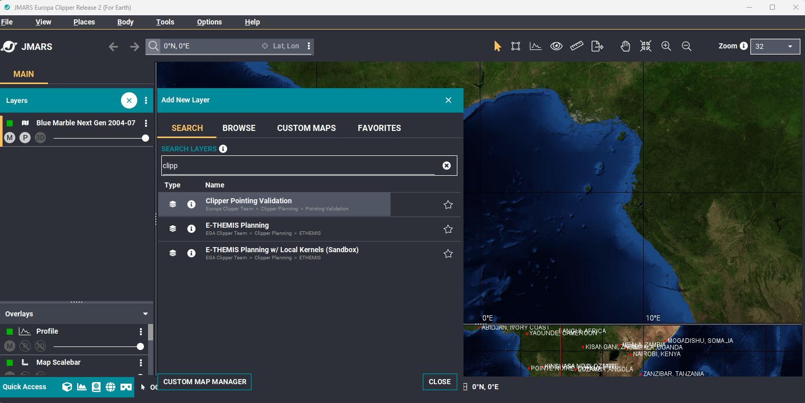
The Add Layer dialog showing the Pointing Validation Layer.
- Select an orbit and wait for the layer to finish loading.
- Verify that the Events ruler appears in the timeline.
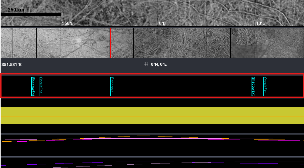
The Events ruler displaying Mission Events in the currently loaded trajectory.
Note: The Events ruler displays events from both the loaded kernel set and the Mission Events file. Events shown in ALL CAPS are provided by the kernel set, while events shown in Proper Case are retrieved from the Mission Events file stored in the database.
Note:There may not be Mission Events available for every selected plan time range.
Events Ruler Context Menu
Like the other rulers in the Pointing Validation Layer, the Events ruler provides a context menu when right-clicked. From this menu, users can:
- Zoom to a selected time range.
- Jump to a selected time.
- Hide or unhide the ruler.
- Open the Properties dialog to configure event display options.
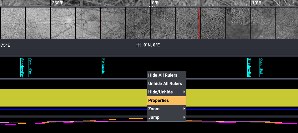
The Events ruler context menu with the Properties option highlighted.
Events Properties
Select Properties from the Events ruler context menu to configure the Events ruler. Individual event types can be enabled or disabled, and the event display color can be customized.
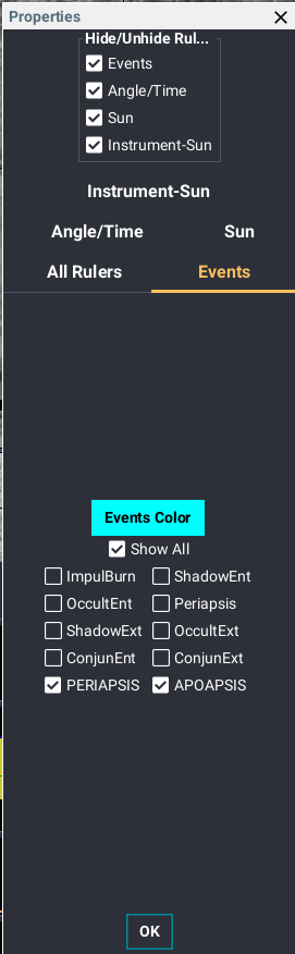
The Events Properties dialog showing event visibility and color configuration options.
Expected Result:
The Events ruler is populated with events from the currently loaded trajectory. Users can navigate the ruler from its context menu and configure which event types are displayed through the Properties dialog.
New Angle Measurements
Delivery 2 adds several new angle measurements to the Angle/Time ruler, providing additional observation geometry for mission planning and analysis.
The Phase Angle and Emission Angle at the sub-spacecraft point are now available regardless of the selected target body.
When Earth is the selected observation target, the Sun-Earth-Spacecraft angle becomes available.
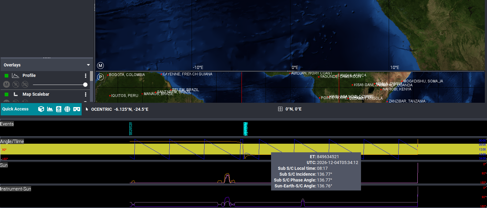
The Angle/Time ruler displaying the Sun-Earth-Spacecraft angle.
When observing one of the Galilean moons, the Sun-Jupiter-Spacecraft angle becomes available.
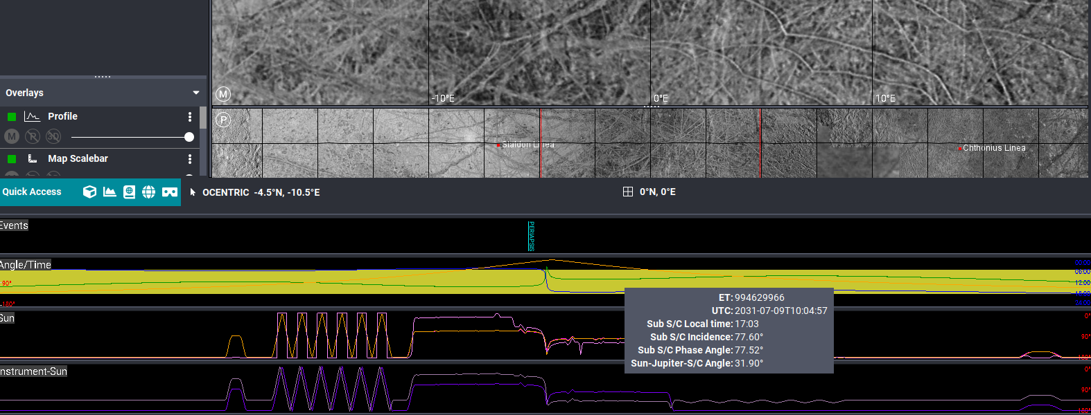
The Angle/Time ruler displaying the Sun-Jupiter-Spacecraft angle.
All of these measurements can be enabled, disabled, and assigned custom colors through the ruler Properties dialog. To open the Properties dialog, right-click a ruler and select Properties.
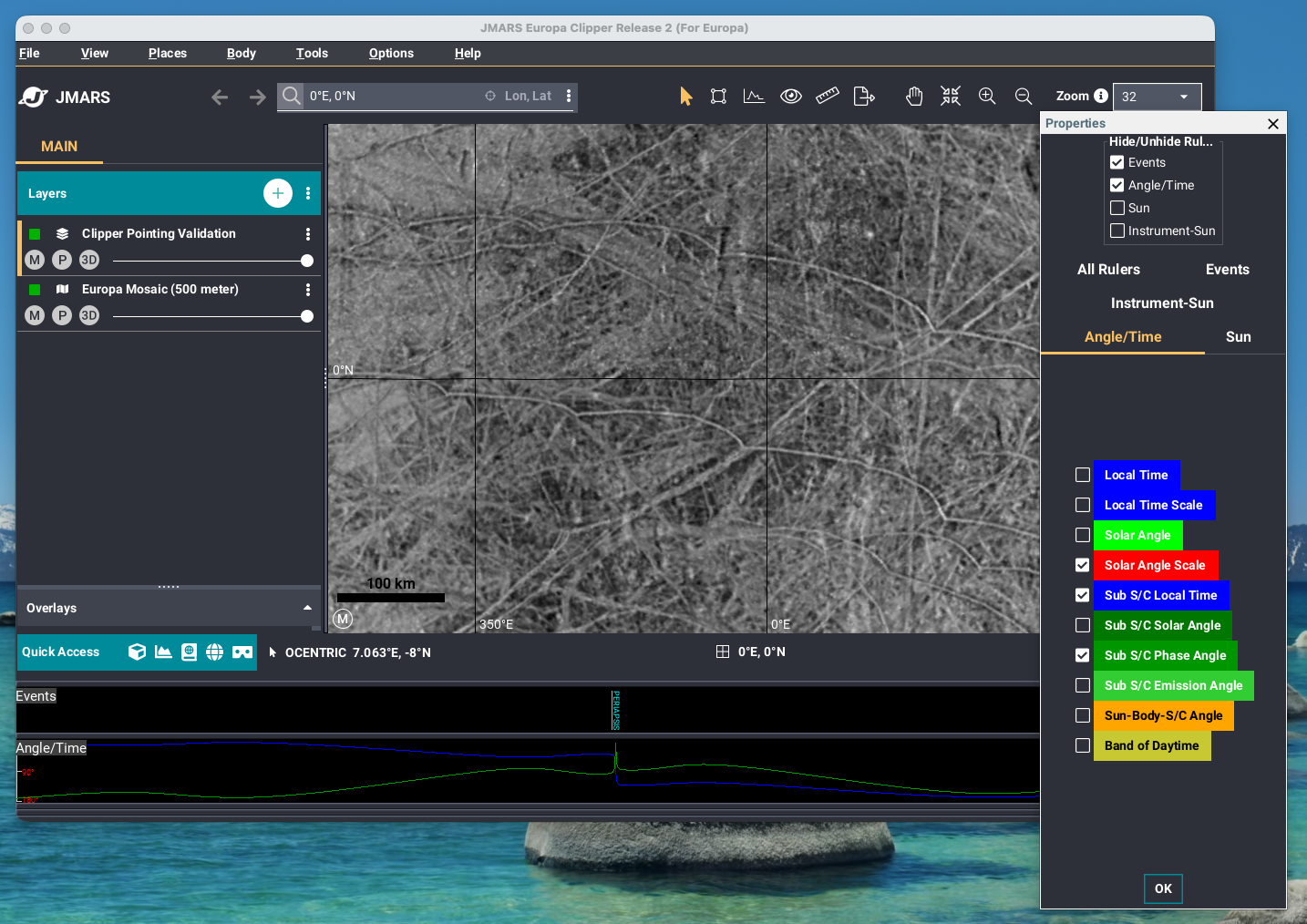
The Ruler Properties dialog showing the available angle display options.
Expected Result:
The newly added angle measurements appear in the Angle/Time ruler and update dynamically based on the selected observation target.
Instrument-Sun Ruler
Delivery 2 adds a new Instrument-Sun ruler that displays the separation angle between each instrument boresight and the Sun. Users can select different instruments to view the separation angle from the selected instrument's boresight to the Sun.
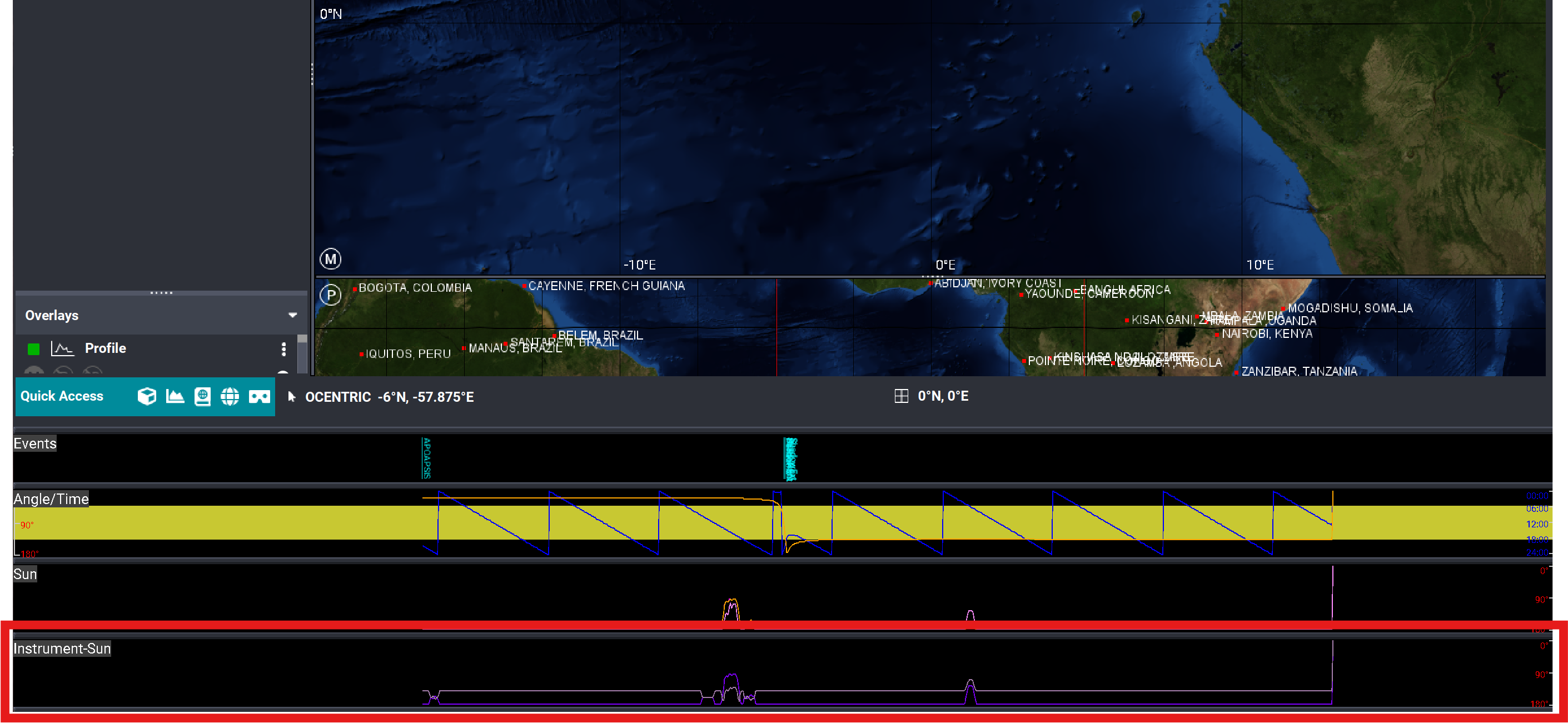
The Instrument-Sun ruler displaying the separation angle between the selected instrument boresight and the Sun.
Instrument-Sun Ruler Context Menu
Like the other rulers in the Pointing Validation Layer, the Instrument-Sun ruler provides a context menu when right-clicked. From this menu, users can:
- Zoom to a selected time range.
- Jump to a selected time.
- Hide or unhide the ruler.
- Open the Properties dialog to configure the ruler.
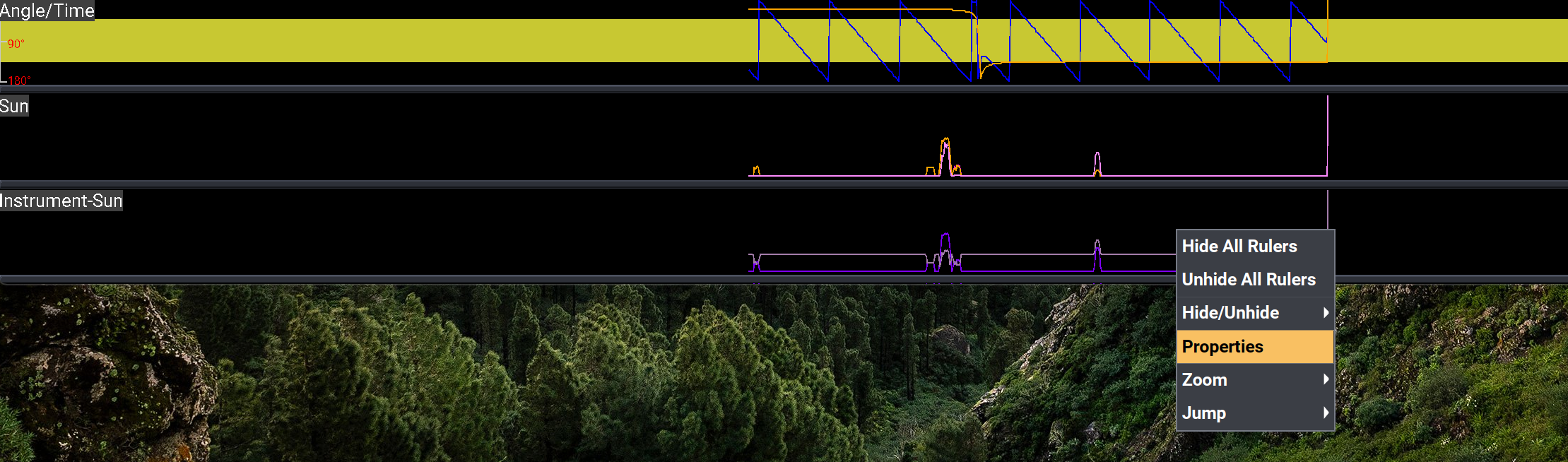
The Instrument-Sun ruler context menu with the Properties option highlighted.
Instrument-Sun Properties
Select Properties from the Instrument-Sun ruler context menu to configure the displayed instruments. Individual instruments can be enabled or disabled, and each instrument can be assigned a custom display color.
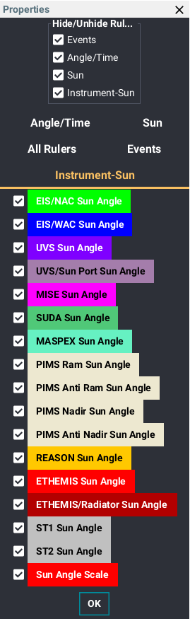
The Instrument-Sun Properties dialog showing instrument visibility and color configuration options.
Expected Result:
The Instrument-Sun ruler displays the separation angle between the selected instrument boresight and the Sun. Users can navigate the ruler using the context menu or customize the displayed instruments and colors through the Properties dialog.
Additional Display and Configuration Options
Delivery 2 changes the default starting time of the Pointing Validation Layer to the spacecraft's closest approach to the selected target body. Depending on the viewing geometry, the spacecraft may appear much smaller. If the spacecraft is difficult to see, it can be made easier to locate by zooming the 3D view, moving forward or backward in time, increasing the Spacecraft Scale, or using any combination of these methods.
- Open the Layer Manager and select the Clipper Pointing Validation layer.
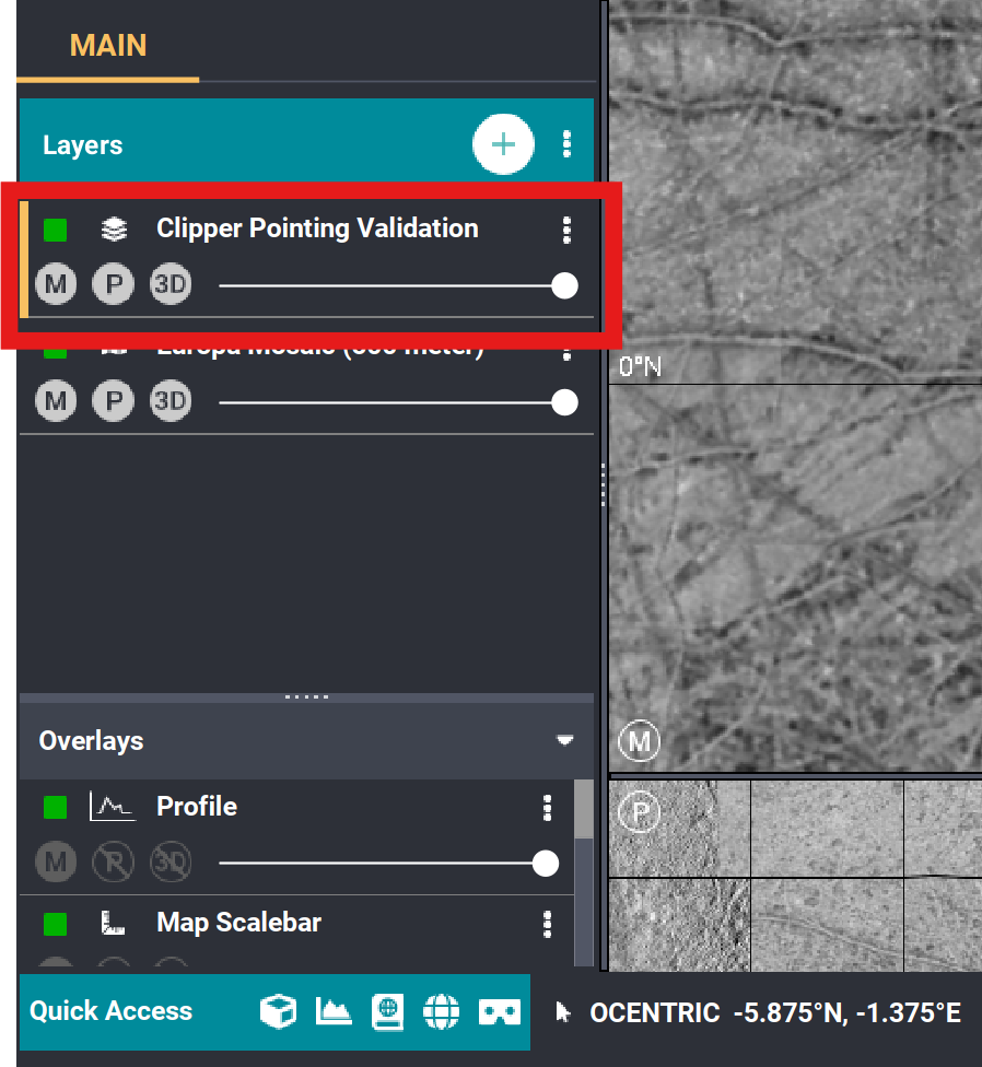
Select the Clipper Pointing Validation layer from the Layer Manager.
The spacecraft can be moved forward or backward in time using the timeline controls. Changing the current time changes the spacecraft's position and viewing geometry, which may make the spacecraft easier to locate.
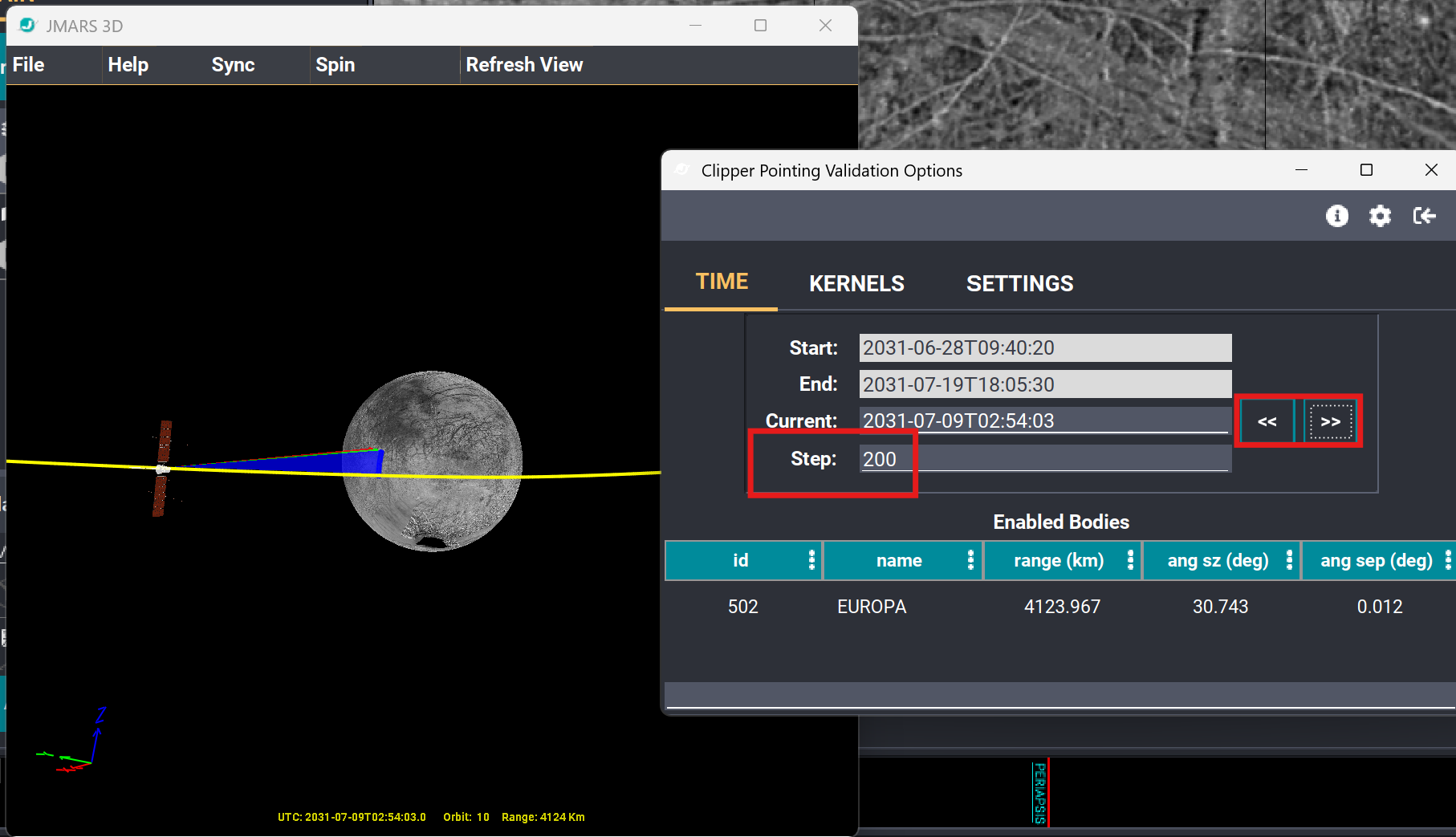
Moving forward or backward in time changes the spacecraft's position and viewing geometry. Altering the Step value increases or decreases the amount of movement per click.
- To change the displayed size of the spacecraft, select the Settings tab.
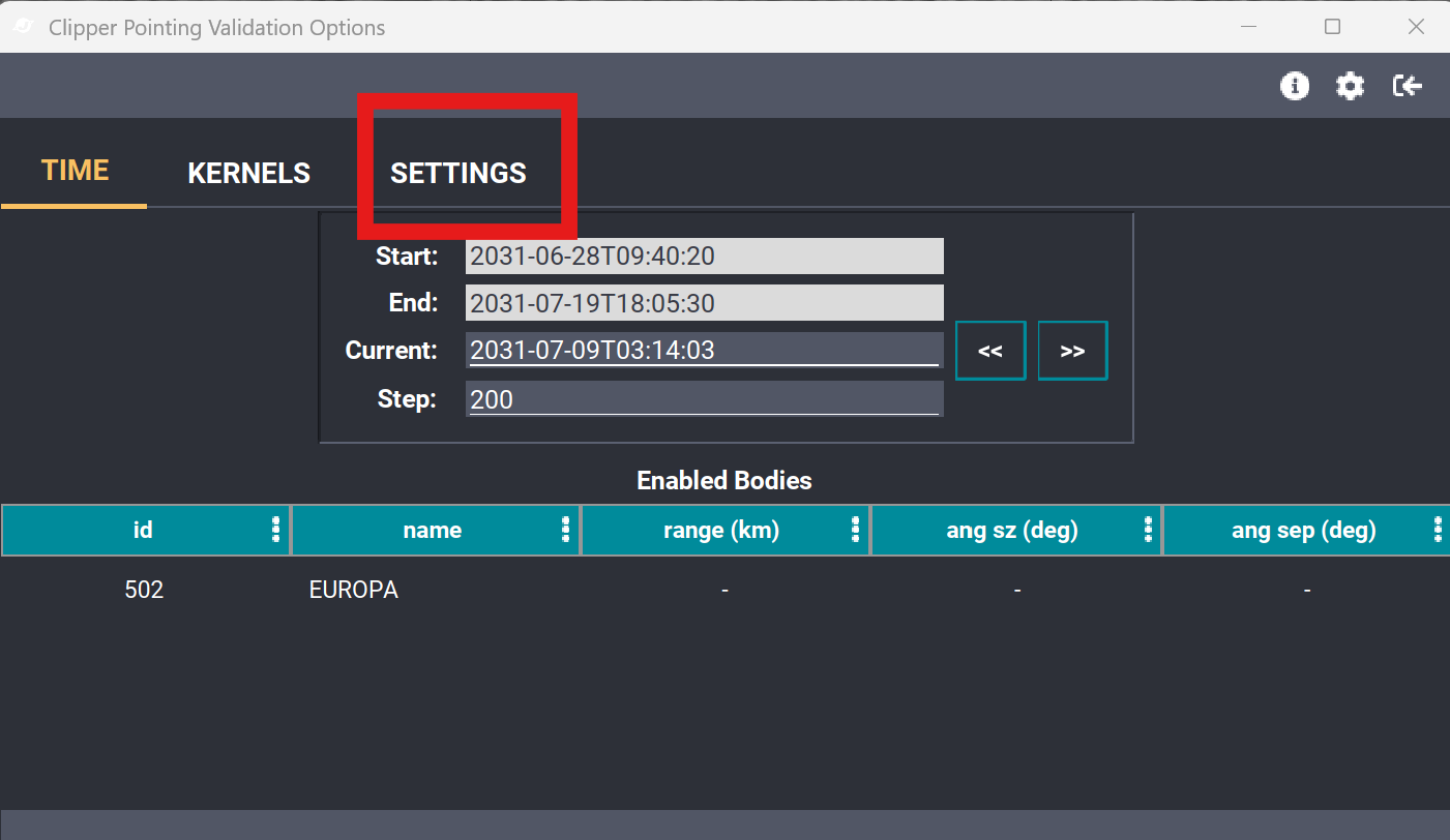
The Settings tab contains the Spacecraft Scale option used to adjust the displayed size of the spacecraft.
Increase or decrease the Spacecraft Scale value until the spacecraft is displayed at the desired size.
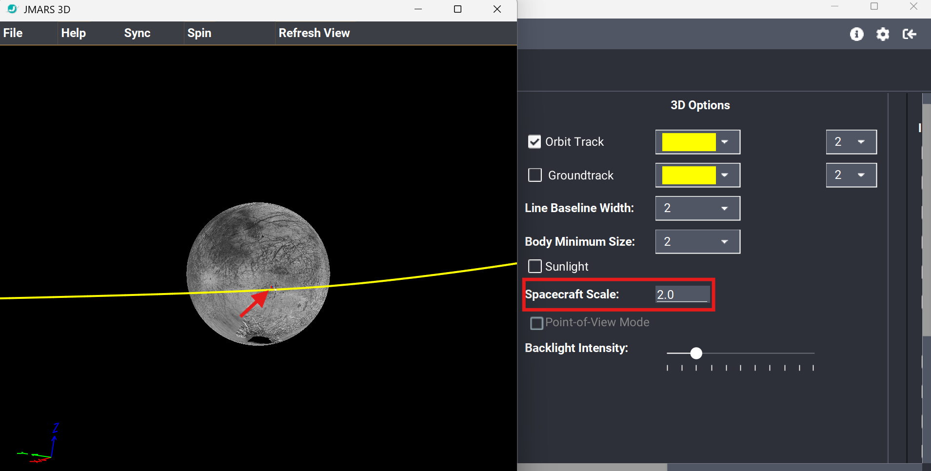
Default Spacecraft Scale value of 2.0.
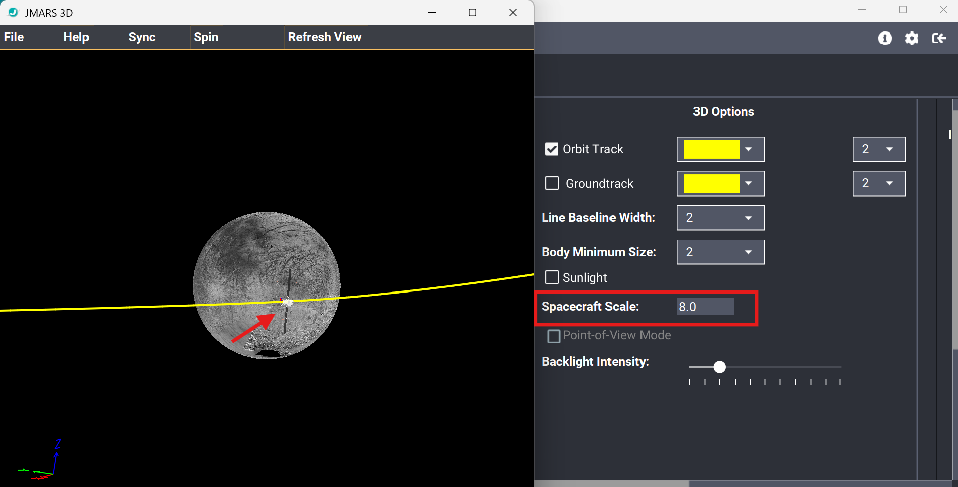
Increasing the Spacecraft Scale value to 8.0 makes the spacecraft easier to see.
Expected Result:
The spacecraft is clearly visible in the 3D view. Users can improve visibility by zooming the 3D view, changing the current time, increasing the Spacecraft Scale, or using any combination of these methods.