
- Home
- Getting Started
- Documentation
- Release Notes
- Tour the Interface
- Tour the Layers
- JMARS Video Tutorials
- Lat/Lon Grid Layer
- Map Scalebar
- Nomenclature
- Crater Counting
- 3D
- Shape Layer
- Mosaics
- Map
- Advanced/Custom Maps
- Graphic/Numeric Maps
- Custom Map Sharing
- Stamp
- THEMIS
- MOC
- Viking
- CRISM Stamp Layer
- CTX
- HiRise
- HiRISE Anaglyph
- HiRISE DTM
- HRSC
- OMEGA
- Region of Interest
- TES
- THEMIS Planning
- Investigate Layer
- Landing Site Layer
- Tutorials
- Video Tutorials
- Displaying the Main View in 3D
- Finding THEMIS Observation Opportunities
- Submitting a THEMIS Region of Interest
- Loading a Custom Map
- Viewing TES Data in JMARS
- Using the Shape Layer
- Shape Layer: Intersect, Merge, and Subtract polygons from each other
- Shape Layer: Ellipse Drawing
- Shape Layer: Selecting a non-default column for circle-radius
- Shape Layer: Selecting a non-default column for fill-color
- Shape Layer: Add a Map Sampling Column
- Shape Layer: Adding a new color column based on the values of a radius column
- Shape Layer: Using Expressions
- Using JMARS for MSIP
- Introduction to SHARAD Radargrams
- Creating Numeric Maps
- Proxy/Firewall
- JMARS Shortcut Keys
- JMARS Data Submission
- FAQ
- Open Source
- References
- Social Media
- Podcasts/Demos
- Download JMARS
Delivery 4
Delivery 4 - TAT 26.10.1
Delivery 4 introduces new tools and display improvements for the Clipper Pointing Validation layer. This tutorial shows where to find some of the updates and how to use them.
Select a Start and End Orbit
When adding a Clipper Pointing Validation layer, you can now select both a start orbit and an end orbit to define the plan range.
- Add the Clipper Pointing Validation layer from the Add Layer menu in the Layer Manager.
- In the dialog, select the desired Kernel set.
- Choose the Start Orbit and End Orbit for the range you want to load.
- Click Continue and wait for the layer to finish loading.
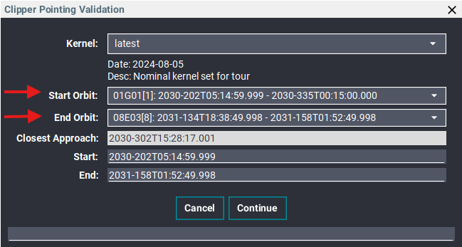
Select the start and end orbits when adding the layer.
Point of View Updates
Point-of-View Mode is now located in the Time tab. Enable it to view the scene from the spacecraft’s perspective.
- Double-click the Clipper Pointing Validation layer in the Layer Manager to open the options dialog.
- Select the Time tab.
- Select the Point-of-View Mode checkbox on the right.
Use the arrow controls to adjust X Off (deg) and Y Off (deg). The X/Y Step (deg) value controls the size of each adjustment. The middle dot button resets the offsets.
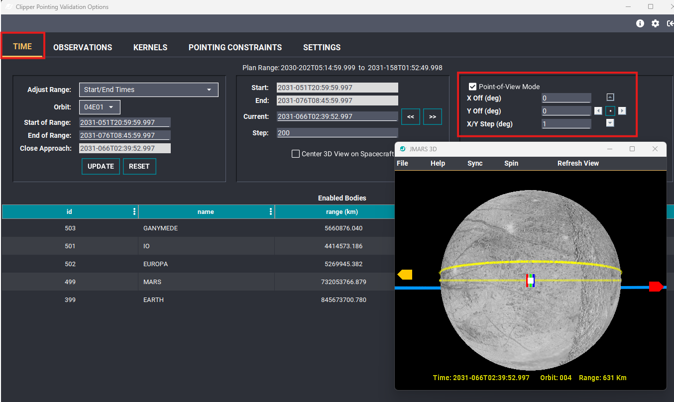
Point-of-View Mode is now on the right side of the Time tab.
Center the 3D View on the Spacecraft
The spacecraft-centering control is also now in the Time tab.
- If your Time tab is not already open, double-click the Clipper Pointing Validation layer and select Time.
- Select Center 3D View on Spacecraft beneath the current-time controls to center the 3D view on the spacecraft.
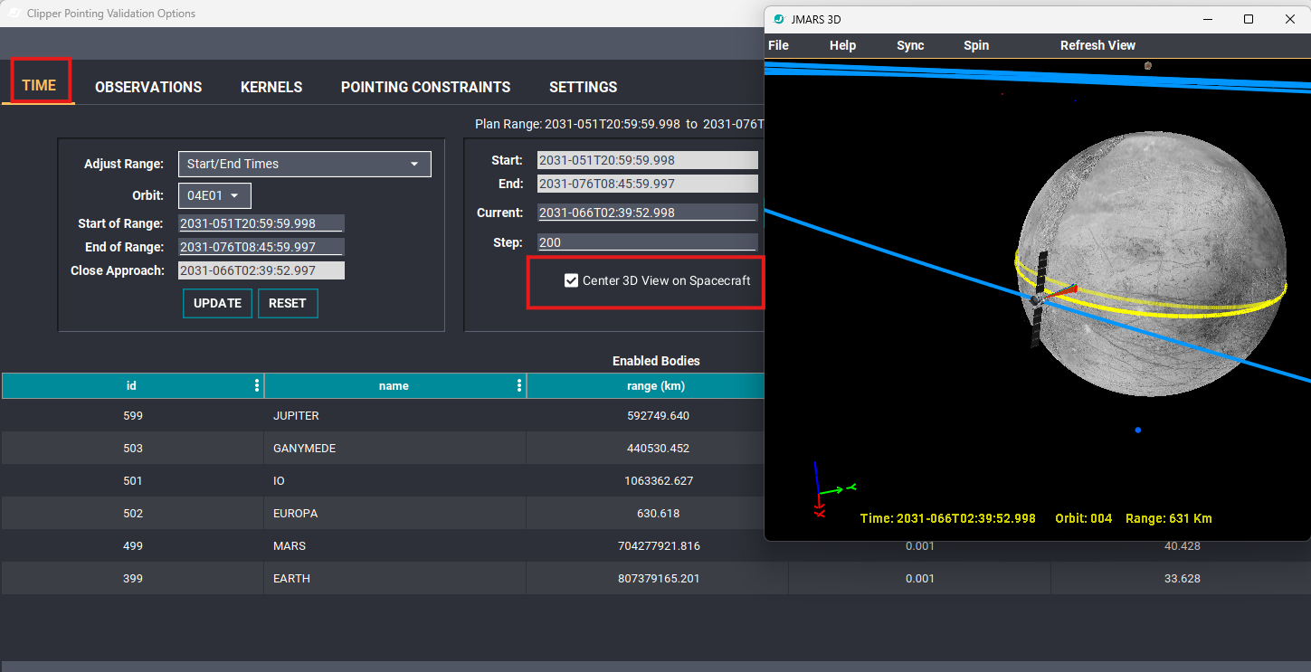
Select Center 3D View on Spacecraft in the Time tab to center the 3D view on the spacecraft.
Adjust the Time Range
The Adjust Range panel is the first box on the left in the Time tab. Use it to select the times or durations shown by the ground track and orbit track. Three options are available.
Start/End Times
- Select Start/End Times from the Adjust Range menu.
- Choose the desired Orbit.
- Change Start of Range and End of Range if desired.
- Click UPDATE to display the revised range in the 3D view.
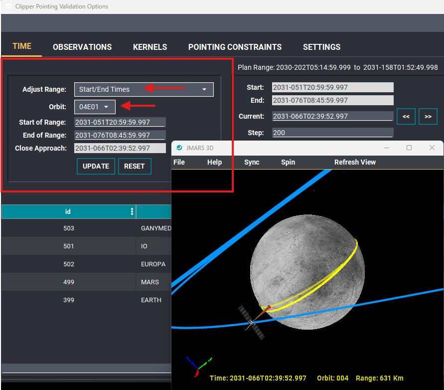
Choose an orbit and adjust its start and end times. Click UPDATE to apply the range.
Start Time With Duration
Use this option to display a specific number of minutes beginning at a selected start time.
- Select Start Time With Duration from the Adjust Range menu.
- Choose the desired Orbit and change Start of Range if needed.
- Enter the desired Duration (min).
- Click UPDATE to apply the new range.
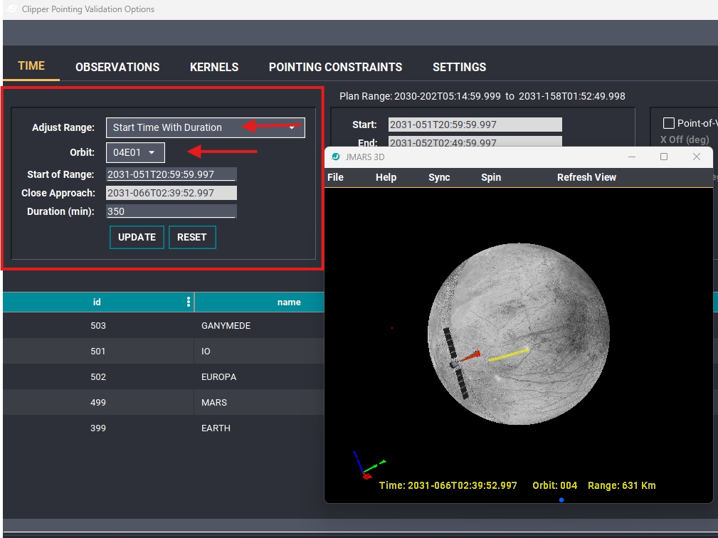
Specify a start time and duration in minutes to control the displayed track range.
Close Approach-relative Start
Use this option to define a start time relative to the selected orbit’s close approach, then specify how many minutes to display in either direction.
- Select Close Approach-relative Start from the Adjust Range menu.
- Choose the desired Orbit.
- Enter a time offset in CA Delta (min).
- Enter the desired Duration (min).
- Click UPDATE to apply the new range.
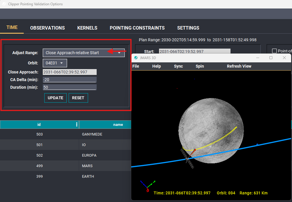
This example begins 20 minutes before close approach and displays a 50-minute range.
CA Delta: Enter a negative number of minutes to begin before close approach, or a positive number to begin after close approach. Enter 0 to begin at close approach. For example, -20 begins 20 minutes before close approach, while 20 begins 20 minutes after it.
Hover over CA Delta (min) to display a tooltip explaining the offset.
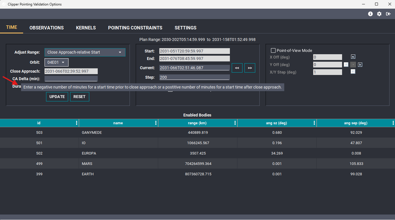
Hover over CA Delta (min) for guidance on setting the start time relative to close approach.
Organized Kernel Sets and Clipboard Copy
The Kernels tab now groups kernels into organized sets instead of displaying a single list.
- Open the layer options dialog and select Kernels.
- Expand a group to view its kernels, or collapse it to hide the entries.
- Click Copy Kernel List to copy the kernel list to the clipboard.
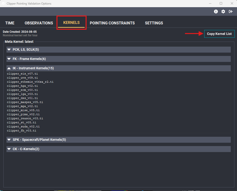
Kernels are grouped by type, and Copy Kernel List copies the list to the clipboard.
Display the MASPEX Instrument
MASPEX has been added to the instrument controls in the Settings tab.
- Open the layer options dialog and select Settings.
- In the instrument controls on the right, expand In situ.
- Select the MASPEX checkbox to display the instrument in the 3D view.
MASPEX Display Updates
- A colorized arrow points away from the spacecraft in the direction of the velocity vector (ram).
- A filled circle is drawn on the surface directly below the spacecraft. Its radius equals the spacecraft’s elevation above the surface.

Select MASPEX in the Settings tab to display it in the 3D view.
Create and Review Observations
The new Observations tab allows you to create mosaics and review their image locations in the 3D view.
Generate an Observation
- Open the layer options dialog and select Observations.
- Enter an Observation Time, or click Copy Current SC Time to copy the current spacecraft time into that field.
- Select the Observation Type, Target Body, and Instrument. Adjust the other observation settings as needed.
- Select Show Vectors to display vectors showing where the images are being taken.
- Click Generate Observation.
Review Multiple Observations
Generated observations appear in the Observation Results table. Select an observation in the table to display it in the 3D view.
If observations were generated at different times, select the desired observation and optionally click Set Current SC Time to update the current spacecraft time to that observation’s time.
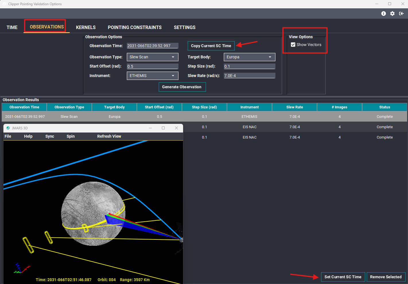
Generate observations, select a result to display it, and use Set Current SC Time when you want to match the spacecraft time to the selected observation.
Background Stars in the 3D View
Background stars can now be displayed individually or as a full star field in the 3D view.
Show the Full Star Field
- Open the layer options dialog and select Settings.
- At the bottom of the 3D Options panel in the middle, select Show Stars to enable the full star field.
- Use the color control to change the star color, and adjust Star magnitude limit to control which stars are displayed based on their brightness.
Show Individual Named Stars
On the left, expand Named Stars to turn any of the following three stars on or off and set their colors:
- Beta Leonis
- Beta Orionis
- Eta Carinae
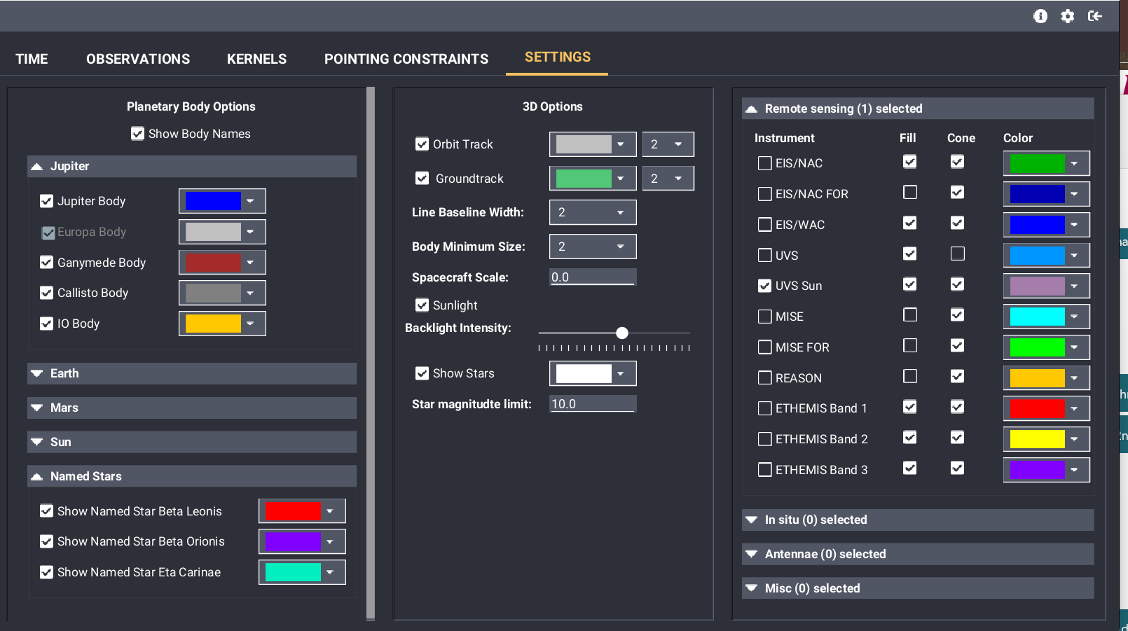
Use Show Stars for the full star field, or enable individual stars under Named Stars.
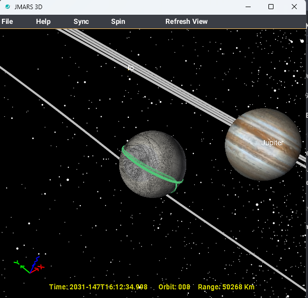
Background stars displayed in the 3D view.
Performance note: Displaying a large number of stars may reduce performance in the 3D view as you move through time.
Pointing Constraints Update
New Checks for Pointing Constraints
The Pointing Constraints checks now include the Field of Regard (FOR) for:
- MISE
- EIS/NAC
- Open the layer options dialog and select Pointing Constraints.
- Select the desired instrument from the Instrument menu.
- Set the start time, end time, and checking interval as needed, then click BEGIN CONSTRAINT CHECKS.
- Review the Status summary and results table for the Field of Regard checks and any detected violations.
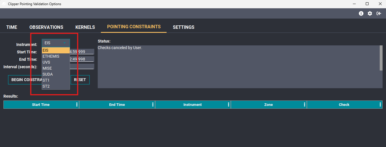
Select an instrument in the Pointing Constraints tab.
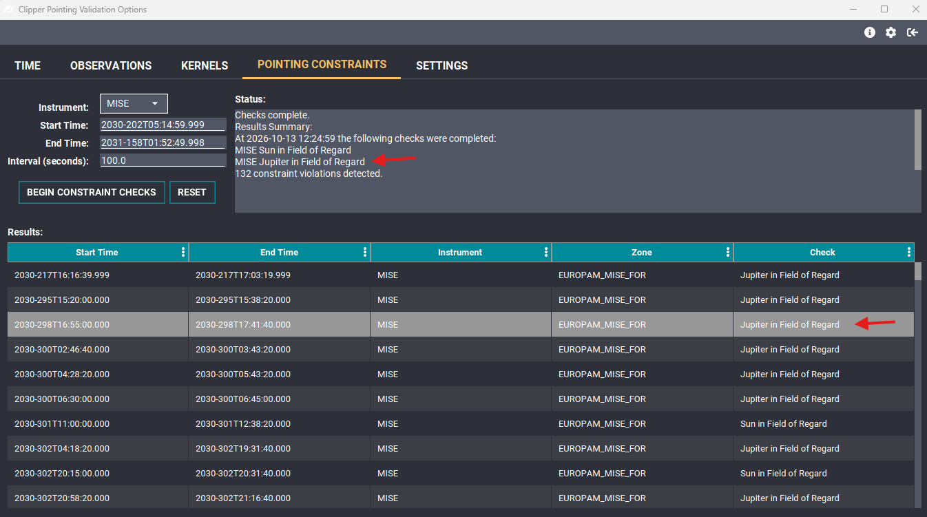
The status summary and results table include MISE Field of Regard checks.
New Appearance for Non-Remote-Sensing Instruments
All non-remote-sensing instrument fields of view (FOVs) are displayed as fixed-length cones. These cones are always depicted as “off body,” even when they point at the target body.
When the 3D spacecraft model is made larger or smaller, the non-remote-sensing FOVs and cones scale to match.
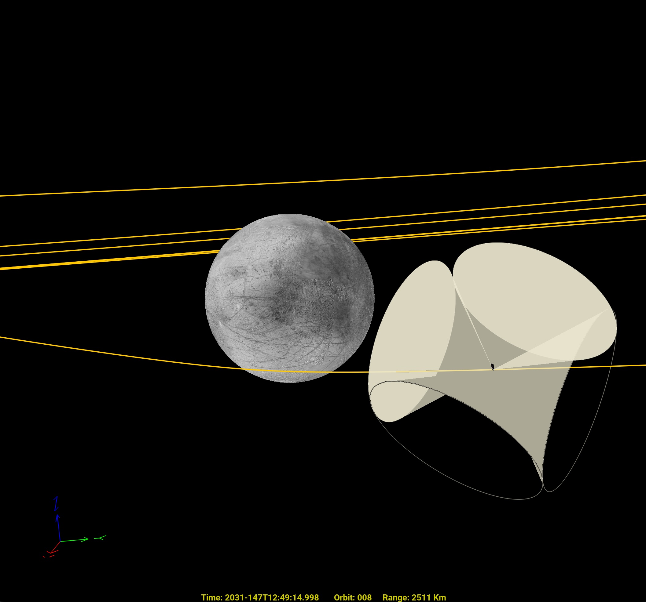
All four PIMS cones are displayed off body and scale with the spacecraft model.
Missing CK Data
When spacecraft orientation data from CK kernels are unavailable, the spacecraft rotates so that the instrument deck points toward nadir.
If there are no CK data at the current time, the 3D view displays No CK Data for Current Time in red.