
- Home
- Getting Started
- Documentation
- Release Notes
- Tour the Interface
- Tour the Layers
- JMARS Video Tutorials
- Lat/Lon Grid Layer
- Map Scalebar
- Nomenclature
- Crater Counting
- 3D
- Shape Layer
- Mosaics
- Map
- Advanced/Custom Maps
- Graphic/Numeric Maps
- Custom Map Sharing
- Stamp
- THEMIS
- MOC
- Viking
- CRISM Stamp Layer
- CTX
- HiRise
- HiRISE Anaglyph
- HiRISE DTM
- HRSC
- OMEGA
- Region of Interest
- TES
- THEMIS Planning
- Investigate Layer
- Landing Site Layer
- Tutorials
- Video Tutorials
- Displaying the Main View in 3D
- Finding THEMIS Observation Opportunities
- Submitting a THEMIS Region of Interest
- Loading a Custom Map
- Viewing TES Data in JMARS
- Using the Shape Layer
- Shape Layer: Intersect, Merge, and Subtract polygons from each other
- Shape Layer: Ellipse Drawing
- Shape Layer: Selecting a non-default column for circle-radius
- Shape Layer: Selecting a non-default column for fill-color
- Shape Layer: Add a Map Sampling Column
- Shape Layer: Adding a new color column based on the values of a radius column
- Shape Layer: Using Expressions
- Using JMARS for MSIP
- Introduction to SHARAD Radargrams
- Creating Numeric Maps
- Proxy/Firewall
- JMARS Shortcut Keys
- JMARS Data Submission
- FAQ
- Open Source
- References
- Social Media
- Podcasts/Demos
- Download JMARS
New MOC Stamp Layer
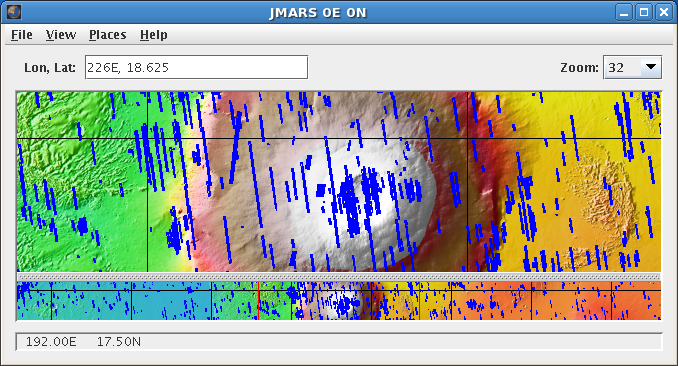
The MOC Stamp Layer will display stamps for all of the images taken by the Mars Orbital Camera (MOC) aboard Mars Global Surveyor. While the search interface is similar to the THEMIS Stamp Layer, there are changes that allow users to search for images by the many parameters associated with MOC images.
Open the MOC Stamp Layer
-
- Open the Stamp Layer: Chose "Add New Layer" -> "Stamps" -> "MOC Stamps".
- Enter Search Parameters: An input box will appear with all of the available search parameters. It is not necessary to enter values for each parameter, but the more specific your search the faster it will be. The allowable values for each field are given in the quick reference table below followed by more detailed descriptions of each search parameter.
- Perform Image Search: Clicking OK will make the Stamp Layer perform the search and display the results. Depending on how specific the search parameters are, it may take the Stamp Layer a few minutes to find and create stamps for all of the images. Once the stamps are displayed in the Viewing Window, users can right-click on an outline to either render the image (display the image data in JMARS) or view the image in a web browser.

| Image ID(s) | Any Image ID Numbers |
| Instrument | MOC-NA - MOC Narrow Angle Camera MOC-WA - MOC Wide Angle Camera Blank - Both Instruments |
| Filter | Blue Red N/A Blank - All Filter Types |
| Mission Phase | AB-1 - Aerobraking Phase 1 Extended - Extended Mission Phase Mapping - Mapping Phase Relay - Relay Phase SPO-1 SPO-2 Support Blank - All Mission Phases |
| Min/Max Longitude | 0 - 360 - East Longitude = Positive, West Longitude = Negative Blank - All Longitudes |
| Min/Max Latitude | 90 - -90 - North Latitude = Positive, South Latitude = Negative Blank - All Latitudes |
| Min/Max Orbit | Any Orbit Range Blank - All Orbits |
| Downtrack Summing | 1 - Wide-Angle ~ 250m resolution, Narrow-Angle ~ 1.5m resolution 2 - Wide-Angle ~ 500m resolution, Narrow-Angle ~ 3.0m resolution 3 - Wide-Angle ~ 750m resolution, Narrow-Angle ~ 4.5m resolution 3 - Wide-Angle ~ 1,000m resolution, Narrow-Angle ~ 6.0m resolution 5 - Wide-Angle ~ 1,250m resolution, Narrow-Angle ~ 7.5m resolution 6 - Wide-Angle ~ 1,500m resolution, Narrow-Angle ~ 9.0m resolution 8 - Wide-Angle ~ 2,000m resolution, Narrow-Angle ~ 12.0m resolution 13 - Wide-Angle ~ 3,250m resolution, Narrow-Angle ~ 19.5m resolution 27 - Wide-Angle ~ 6,750m resolution, Narrow-Angle ~ 40.5m resolution 30 - Wide-Angle ~ 7,500m resolution, Narrow-Angle ~ 45.0m resolution ALL - All Resolutions |
| Scaled Pixel Width | 1.0 - 7500.0 Blank - Any Scaled Pixel Width |
| Lines | xxx Blank - Any Lines |
| Line Samples | xxx Blank - Any Line Samples |
| Min/Max Solar Longitude | 0 - 360 - 0=Northern Vernal Equinox Blank - All Solar Longitudes |
| Local Time (24hr) | 00:00-24:00 - Given as HH:MM Blank - All Times |
| Min/Max Solar Incidence Angle | 0 - 180 - 0=Sun Directly Overhead, 90=Sun on the Horizon Blank - All Incidence Angles |
| Min/Max Emission Angle | 0 - 180 - 0=MOC Directly Overhead, 90=MOC on the Horizon Blank - All Emission Angles |
| Phase Angle | 0 - 180 - 0=MOC and Sun In-Line, 90=MOC and Sun at 90deg Angle Blank - All Phase Angles |
| Slant Distance | 0 - 5000 - Distance from sub-MGS point to image center (in meters) Blank - All Slant Distances |
| Rationale Description | Any Text Blank - Any Rationale Descriptions |
-
-
- Search Field Descriptions
- Search Field Descriptions
-
-
-
-
- Image ID
- A unique identifier for each image commanded; follows the pattern XXX-ooooo, where:
- a) XXX is a 3-digit mission phase identifier
- b) ooooo is the zero padded, 5 digit image number
- a) XXX is a 3-digit mission phase identifier
- A unique identifier for each image commanded; follows the pattern XXX-ooooo, where:
- Image ID
-
-
-
-
-
- Instrument
- The MOC had two cameras: a narrow-angle and wide-angle. This identifies which camera was used to collect the observations.
- The MOC had two cameras: a narrow-angle and wide-angle. This identifies which camera was used to collect the observations.
- Instrument
-
-
-
-
-
- Filter
- The MOC wide angle camera had both blue and red filters. The MOC narrow angle camera only took unfiltered (N/A) grayscale images.
- The MOC wide angle camera had both blue and red filters. The MOC narrow angle camera only took unfiltered (N/A) grayscale images.
- Filter
-
-
-
-
-
- Mission Phase
- The MOC imaging mission is divided into the following phases:
- AB1 Aerobraking Phase
- SPO-1 First Science Phasing Orbits
- SPO-2 Second Science Phasing Orbits
- Mapping Mapping Phase (First Martian Year)
- Extended Extended Mission Phase (Second Martian Year)
- Relay Relay Mission Phase (Third Martian Year)
- Support Support Mission Phase (Fourth Martian Year)
- AB1 Aerobraking Phase
- The MOC imaging mission is divided into the following phases:
- Mission Phase
-
-
-
-
-
- Longitude
- This is the approximate longitude on the planet Mars of the image center. All values are based on the IAU 2000 aerocentric model of Mars with east positive longitude. (gives in degrees of East Longitude)
- This is the approximate longitude on the planet Mars of the image center. All values are based on the IAU 2000 aerocentric model of Mars with east positive longitude. (gives in degrees of East Longitude)
- Longitude
-
-
-
-
-
- Latitude
- This is the approximate latitude on the planet Mars of the image center. All values are based on the IAU 2000 aerocentric model of Mars with east positive longitude.
- This is the approximate latitude on the planet Mars of the image center. All values are based on the IAU 2000 aerocentric model of Mars with east positive longitude.
- Latitude
-
-
-
-
-
- Orbit
- Spacecraft orbit during which this image was observed. By definition, orbits begin at the ascending equator crossing of Global Surveyor's polar orbit.
- Spacecraft orbit during which this image was observed. By definition, orbits begin at the ascending equator crossing of Global Surveyor's polar orbit.
- Orbit
-
-
-
-
-
- Downtrack Summing
- Spatial average of NxN pixels of data before downlink; summing=1 implies that no spatial averaging has been applied. In all but a few unusual images, the crosstrack summing was set at the same value as the downtrack summing.
- Spatial average of NxN pixels of data before downlink; summing=1 implies that no spatial averaging has been applied. In all but a few unusual images, the crosstrack summing was set at the same value as the downtrack summing.
- Downtrack Summing
-
-
-
-
-
- Scaled Pixel Width
- This is the image resolution in meters per pixel at the center of the image. For most narrow angle images, this value will be approximately the same over the entire picture. For wide angle images, the pixel scale will vary over the image.
- This is the image resolution in meters per pixel at the center of the image. For most narrow angle images, this value will be approximately the same over the entire picture. For wide angle images, the pixel scale will vary over the image.
- Scaled Pixel Width
-
-
-
-
-
- Lines
- Lines
-
-
-
-
-
- Line Samples
- Line Samples
-
-
-
-
-
- Solar Longitude
- This is the position of Mars relative to the Sun measured in degrees from the vernal equinox (start of northern Spring). This number is used as a measure of Martian seasons. (Also known as heliocentric longitude and abbreviated Ls.)
- a) Northern Spring/Southern Autumn start at 0°
- b) Northern Summer/Southern Winter start at 90°
- c) Northern Autumn/Southern Spring start at 180°
- d) Northern Winter/Southern Summer begin at 270°
- a) Northern Spring/Southern Autumn start at 0°
- This is the position of Mars relative to the Sun measured in degrees from the vernal equinox (start of northern Spring). This number is used as a measure of Martian seasons. (Also known as heliocentric longitude and abbreviated Ls.)
- Solar Longitude
-
-
-
-
-
- Local Time'
- This is the local time on Mars at the center of the image relative to a division of the martian day into 24 equal parts. A martian day is slightly longer than 24 hours and 37 minutes long.
- This is the local time on Mars at the center of the image relative to a division of the martian day into 24 equal parts. A martian day is slightly longer than 24 hours and 37 minutes long.
- Local Time'
-
-
-
-
-
- Incidence Angle
- Derived for the center of the image, this is the angle between the Sun and a "normal" drawn perpendicular to the planet's surface at the time the image was acquired. A higher incidence angle means that a person standing on the ground would see the sun lower toward the horizon.
- Derived for the center of the image, this is the angle between the Sun and a "normal" drawn perpendicular to the planet's surface at the time the image was acquired. A higher incidence angle means that a person standing on the ground would see the sun lower toward the horizon.
- Incidence Angle
-
-
-
-
-
- Emission Angle
- Measured from the center of the image, this is the angle between the MOC and a "normal" drawn perpendicular to the planet's surface. In most cases, the MOC is looking "straight down" and the emission angle is thus close to 0°.
- Measured from the center of the image, this is the angle between the MOC and a "normal" drawn perpendicular to the planet's surface. In most cases, the MOC is looking "straight down" and the emission angle is thus close to 0°.
- Emission Angle
-
-
-
-
-
- Phase Angle
- This is the angle between the sun, the surface, and the MOC at the time the picture was obtained.
- This is the angle between the sun, the surface, and the MOC at the time the picture was obtained.
- Phase Angle
-
-
-
-
-
- Slant Distance
- This number is similar to the spacecraft altitude, but also takes into account the emission angle. If the emission angle is 0 then this number is the same as the spacecraft altitude. If the emission angle is much greater than 0, then the "slant distance" to the surface at the center of the image is also greater than the spacecraft altitude.
- This number is similar to the spacecraft altitude, but also takes into account the emission angle. If the emission angle is 0 then this number is the same as the spacecraft altitude. If the emission angle is much greater than 0, then the "slant distance" to the surface at the center of the image is also greater than the spacecraft altitude.
- Slant Distance
-
-
-
-
-
- Rationale Description
- A short description of why the image was targeted.
- A short description of why the image was targeted.
- Rationale Description
-
-
Stamp Layer Functions
- The MOC Stamp Layer's functions are identical to the functions of the Thermal Emission Image System (THEMIS) Stamp Layer and are explained in detail on its wiki page.