
- Home
- Getting Started
- Documentation
- Release Notes
- Tour the Interface
- Tour the Layers
- JMARS Video Tutorials
- Lat/Lon Grid Layer
- Map Scalebar
- Nomenclature
- Crater Counting
- 3D
- Shape Layer
- Mosaics
- Map
- Advanced/Custom Maps
- Graphic/Numeric Maps
- Custom Map Sharing
- Stamp
- THEMIS
- MOC
- Viking
- CRISM Stamp Layer
- CTX
- HiRise
- HiRISE Anaglyph
- HiRISE DTM
- HRSC
- OMEGA
- Region of Interest
- TES
- THEMIS Planning
- Investigate Layer
- Landing Site Layer
- Tutorials
- Video Tutorials
- Displaying the Main View in 3D
- Finding THEMIS Observation Opportunities
- Submitting a THEMIS Region of Interest
- Loading a Custom Map
- Viewing TES Data in JMARS
- Using the Shape Layer
- Shape Layer: Intersect, Merge, and Subtract polygons from each other
- Shape Layer: Ellipse Drawing
- Shape Layer: Selecting a non-default column for circle-radius
- Shape Layer: Selecting a non-default column for fill-color
- Shape Layer: Add a Map Sampling Column
- Shape Layer: Adding a new color column based on the values of a radius column
- Shape Layer: Using Expressions
- Using JMARS for MSIP
- Introduction to SHARAD Radargrams
- Creating Numeric Maps
- Proxy/Firewall
- JMARS Shortcut Keys
- JMARS Data Submission
- FAQ
- Open Source
- References
- Social Media
- Podcasts/Demos
- Download JMARS
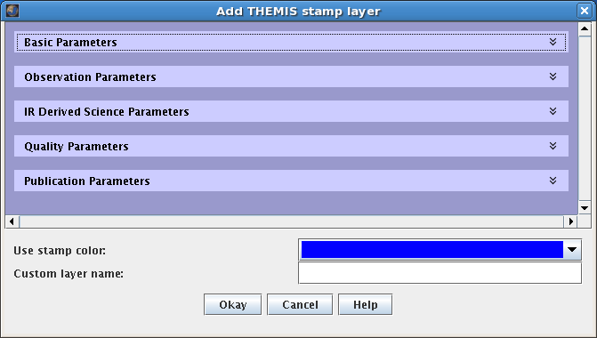
New THEMIS Stamp Layer
The THEMIS Stamp Layer will display outlines (or "stamps") for all VIS and IR observations taken by the THEMIS camera. Since the THEMIS dataset is so large, there are numerous search parameters that allow users to retrieve stamps for only the observations they are interested in.

Open the THEMIS Stamp Layer
-
- Open the Stamp Layer: In the Layer Manager chose "Add New Layer" -> "Stamps" -> "THEMIS Stamps".
-
- Search Parameter Categories: The search parameters are divided into categories since there are so many of them. Clicking on the down arrow on the right side of the category name will reveal all the search parameters in that category. The categories are:
-
- Basic Parameters
- Observation Parameters
- IR Derived Science Parameters
- Quality Parameters
- Publication Parameters
- NOTE: A search can be done with parameters from multiple categories.
-
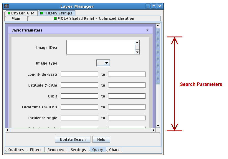
- Enter Search Parameters: It is not necessary to enter values for all parameters, but the more specific your search the faster it will be. The allowable values for each field are given in the quick reference table below.
-
- Perform Image Search: Clicking OK will make the Stamp Layer perform the search and display the results. Depending on how specific the search parameters are, it may take the Stamp Layer a few minutes to find and create stamps for all of the images. Once the stamps are displayed in the Viewing Window, users can right-click on an outline to either render the image (display the image data in JMARS) or view the image in a web browser.
| Filter Type | Acceptable Values |
| Basic Parameters | |
| Image ID(s) | Any Specific Image ID Numbers |
| Image Type | Blank - All Observations VIS - Visible Observations IR - Infrared Observations |
| Eastern/Western Longitude | 0 to 360 - Given in Degrees of East Longitude Blank - All Latitudes |
| Min/Max Latitude | 90 to -90 - North Latitude = Positive, South Latitude = Negative Blank - All Latitudes |
| Min/Max Orbit | 816 - Present - No images taken before orbit 816 Blank - All Orbits |
| Local Time (24hr) | 00:00-24:00 - Given as HH:MM Blank - All Times |
| Min/Max Solar Incidence Angle | 0 - 180 - 0=Sun Directly Overhead, 90=Sun on the Horizon Blank - All Incidence Angles |
| Min/Max Solar Longitude | 0 - 360 - 0=Northern Vernal Equinox Blank - All Solar Longitudes |
| Surface Temperature (K) | 0 - 300 - Only applies to IR observations Blank - All Surface Temperatures |
| Observation Parameters | |
| Processing Stage | Blank - All Processing Stages ABR - VIS Apparent Brightness Record BTR - IR Brightness Temperature Record BWS - Browse (PNG) Image EDR - Experimental Data Record Blank - All Surface Temperatures |
| Resolution (km) | 0.016-0.020 - THEMIS High-Resolution VIS 0.034-0.038 - THEMIS Medium-Resolution VIS 0.070-0.074 - THEMIS Low-Resolution VIS 0.098-0.102 - THEMIS High-Resolution IR 0.198-0.202 - THEMIS Medium-Resolution IR 0.398-0.402 - THEMIS Low-Resolution IR Blank - All Resolutions |
| Duration (s) | 1 - 600 Blank - All Durations |
| Bands(s) | 1 - 10 Blank - All Bands |
| Summing | 1 - High Resolution 2 - Medium Resolution 4 - Low Resolution Blank - All Summing Factors |
| Description | Any Text Blank - All Descriptions |
| Mars Year | 25 - present Blank - All Mars Years |
| IR Derived Science Parameters | |
| MOLA Elevation | -10 to +20 - Elevation at the center of the image. Blank - All Elevations |
| Water Ice Opacity | 0.00 - 0.15 - (Typical) Blank - All Descriptions |
| Dust Opacity | 0.00 - 0.25 - (Typical) Blank - All Descriptions |
| Maximum Thermal Inertia Range | 20 - 2000 - As calculated by the Kieffer model. Blank - All TI Values |
| Minimum Thermal Inertia Range | 20 - 2000 - As calculated by the Kieffer model. Blank - All TI Values |
| Quality Parameters | |
| Percent Missing | 0 - 100 - Percentage of lines missing from the observation. Blank - All Descriptions |
| Image Rating | 1 - Unusable 1 - Unusable 2 - Poor 3 - Poor-Fair 4 - Fair 5 - Fair-Good 6 - Good 7 - Very Good Blank - All Ratings |
| IR Calibration Flag | Blank - All Images t - Only images without calibration error flag |
| Publication Parameters | |
| Release ID | 0001 - ~0022 - Only images from given data release Blank - All Images |
| Modification Date | yyyy-dddThh:mm:ss - Date of ISIS QUBE creation in UTC Blank - All Images |
-
-
- Search Field Descriptions
- Search Field Descriptions
-
-
-
-
- Image ID
- A unique identifier for each image commanded; follows the pattern Xoooooiii, where:
- a) X is the image type (I, R, S, or V)
- b) ooooo is the zero padded, 5 digit orbit number
- c) iii is the zero padded, 3 digit image number
- a) X is the image type (I, R, S, or V)
- A unique identifier for each image commanded; follows the pattern Xoooooiii, where:
- Image ID
-
-
-
-
-
- Image Type
- The THEMIS has two camera: a visible and an infrared camera. This identifies which camera was used to collect the observations.
- The THEMIS has two camera: a visible and an infrared camera. This identifies which camera was used to collect the observations.
- Image Type
-
-
-
-
-
- Longitude
- This is the approximate longitude on the planet Mars of the image center. All values are based on the IAU 2000 aerocentric model of Mars with east positive longitude.
- This is the approximate longitude on the planet Mars of the image center. All values are based on the IAU 2000 aerocentric model of Mars with east positive longitude.
- Longitude
-
-
-
-
-
- Latitude
- This is the approximate latitude on the planet Mars of the image center. All values are based on the IAU 2000 aerocentric model of Mars with east positive longitude.
- This is the approximate latitude on the planet Mars of the image center. All values are based on the IAU 2000 aerocentric model of Mars with east positive longitude.
- Latitude
-
-
-
-
-
- Orbit
- Spacecraft orbit during which this image was observed. By definition, orbits begin at the descending equator crossing of Odyssey's polar orbit.
- Spacecraft orbit during which this image was observed. By definition, orbits begin at the descending equator crossing of Odyssey's polar orbit.
- Orbit
-
-
-
-
-
- Local Time'
- This is the local time on Mars at the center of the image relative to a division of the martian day into 24 equal parts. A martian day is slightly longer than 24 hours and 37 minutes long.
- a) "DAY" images are those with a local time of 08:00-20:00 (8am-8pm)
- b) "NIGHT" images are those with a local time of 00:00-07:59 or 20:01-24:59 (0:00-7:59am or 8:01-11:59pm)
- a) "DAY" images are those with a local time of 08:00-20:00 (8am-8pm)
- This is the local time on Mars at the center of the image relative to a division of the martian day into 24 equal parts. A martian day is slightly longer than 24 hours and 37 minutes long.
- Local Time'
-
-
-
-
-
- Incidence Angle
- Derived for the center of the image, this is the angle between the Sun and a "normal" drawn perpendicular to the surface of the planet at the time the image was acquired. An angle of 0 degrees means the Sun is directly overhead and an angle of 90 degrees means the Sun is on the horizon. Daytime infrared images have incidence angles between approximately 0-90 degrees and nighttime infrared images have incidence angles greater than 90 degrees.
- Derived for the center of the image, this is the angle between the Sun and a "normal" drawn perpendicular to the surface of the planet at the time the image was acquired. An angle of 0 degrees means the Sun is directly overhead and an angle of 90 degrees means the Sun is on the horizon. Daytime infrared images have incidence angles between approximately 0-90 degrees and nighttime infrared images have incidence angles greater than 90 degrees.
- Incidence Angle
-
-
-
-
-
- Solar Longitude
- This is the position of Mars relative to the Sun measured in degrees from the vernal equinox (start of northern Spring). This number is used as a measure of Martian seasons. (Also known as heliocentric longitude and abbreviated Ls.)
- a) Northern Spring/Southern Autumn start at 0°
- b) Northern Summer/Southern Winter start at 90°
- c) Northern Autumn/Southern Spring start at 180°
- d) Northern Winter/Southern Summer begin at 270°
- a) Northern Spring/Southern Autumn start at 0°
- This is the position of Mars relative to the Sun measured in degrees from the vernal equinox (start of northern Spring). This number is used as a measure of Martian seasons. (Also known as heliocentric longitude and abbreviated Ls.)
- Solar Longitude
-
-
-
-
-
- Surface Temperature
- Search is based on average surface temperature (in degrees Kelvin) derived from Band 9 in the IR image.
- Search is based on average surface temperature (in degrees Kelvin) derived from Band 9 in the IR image.
- Surface Temperature
-
-
-
-
-
- Processing Stage
- THEMIS observations are available as multiple types of standard data products:
- ABR: Apparent Brightness Record - The ABR is derived from band 3 of a VIS-RDR QUBE (or first available band of the highest calibration product available). This file is a PDS IMAGE object with an attached PDS label.
- BTR: Brightness Temperature Record - The BTR is derived from band 9 of a IR-RDR QUBE (or first available band of the highest calibration product available). See sdpsis.pdf for a summary of the image processing. This file is a PDS IMAGE object with an attached PDS label.
- EDR: Experiment Data Record - This file contains the raw THEMIS science data at the full resolution returned from the spacecraft, time ordered, with duplicates and transmission errors removed. This file is a PDS SPECTRAL_QUBE object with an attached PDS label.
- GEO: Geometrically Registered Record - This file contains the geometric projection of the RDR standard data product; the data is stored as a multispectral ISIS CUBE file and associated with a PDS-style, detached label. Note that additional manipulation of the source data may invalidate the calibrated radiance values.
- RDR: <i>Reduced Data Record - This file contains the radiometrically calibrated version of the THEMIS EDR standard data products. This file is a PDS SPECTRAL_QUBE object with an attached PDS label.
- ABR: Apparent Brightness Record - The ABR is derived from band 3 of a VIS-RDR QUBE (or first available band of the highest calibration product available). This file is a PDS IMAGE object with an attached PDS label.
- THEMIS observations are available as multiple types of standard data products:
- Processing Stage
-
-
-
-
-
- Resolution
- The size of a pixel on the surface. For example, THEMIS high-resolution VIS images are 18m/pixel and THEMIS high-resolution IR images are 100m/pixel.
- The size of a pixel on the surface. For example, THEMIS high-resolution VIS images are 18m/pixel and THEMIS high-resolution IR images are 100m/pixel.
- Resolution
-
-
-
-
-
- Duration
- The length of time (in seconds) requried to collect all frames of all bands in the downlinked image; typical values range from 0.5 to 450.
- The length of time (in seconds) requried to collect all frames of all bands in the downlinked image; typical values range from 0.5 to 450.
- Duration
-
-
-
-
-
- Bands
- Band numbers correspond to each layer contained in an image; up to 10 bands available in an IR image, and up to 5 bands available in a VIS image.
- Band numbers correspond to each layer contained in an image; up to 10 bands available in an IR image, and up to 5 bands available in a VIS image.
- Bands
-
-
-
-
-
- Summing (Spatial)
- Spatial average of NxN pixels of data before downlink; summing=1 implies that no spatial averaging has been applied. VIS images have summing modes of 1, 2, and 4; IR images have summing modes of 1-320.
- Spatial average of NxN pixels of data before downlink; summing=1 implies that no spatial averaging has been applied. VIS images have summing modes of 1, 2, and 4; IR images have summing modes of 1-320.
- Summing (Spatial)
-
-
-
-
-
- Description
- Description of the image given by the mission planner. When selecting by description, all text entered into the field will be directly compared with available descriptions.
- Description of the image given by the mission planner. When selecting by description, all text entered into the field will be directly compared with available descriptions.
- Description
-
-
-
-
-
- Mars Year
- The Mars year during which this image was collected. Following the convention established in Clancy [JGR April 2000, 1999JE001089], the first Themis mapping images were collected during Mars year 25.
- The Mars year during which this image was collected. Following the convention established in Clancy [JGR April 2000, 1999JE001089], the first Themis mapping images were collected during Mars year 25.
- Mars Year
-
-
-
-
-
- MOLA Elevation
- The average elevation value at the center of the image; values are derived from a 2 pixel per degree MOLA elevation map.
- The average elevation value at the center of the image; values are derived from a 2 pixel per degree MOLA elevation map.
- MOLA Elevation
-
-
-
-
-
- Water Ice Opacity
- Average derived water ice opacity (11µm) for a warm, daytime IR image; typical values range from 0.0 to 0.15.
- Average derived water ice opacity (11µm) for a warm, daytime IR image; typical values range from 0.0 to 0.15.
- Water Ice Opacity
-
-
-
-
-
- Dust Opacity
- Average derived dust opacity (9µm) for a warm, daytime IR image; typical values range from 0.05 to 0.25.
- Average derived dust opacity (9µm) for a warm, daytime IR image; typical values range from 0.05 to 0.25.
- Dust Opacity
-
-
-
-
-
- Maximum Thermal Inertia Range
- The range of maximum values for the average thermal inertia for each cold, nighttime IR image, derived using Keiffer's KRC thermal model. Model allows for inertia values between 20 and 2000.
- The range of maximum values for the average thermal inertia for each cold, nighttime IR image, derived using Keiffer's KRC thermal model. Model allows for inertia values between 20 and 2000.
- Maximum Thermal Inertia Range
-
-
-
-
-
- Minimal Thermal Inertia Range
- The range of minimum values for the average thermal inertia for each cold, nighttime IR image, derived using Keiffer's KRC thermal model. Model allows for inertia values between 20 and 2000.
- The range of minimum values for the average thermal inertia for each cold, nighttime IR image, derived using Keiffer's KRC thermal model. Model allows for inertia values between 20 and 2000.
- Minimal Thermal Inertia Range
-
-
-
-
-
- Percent Missing
- Percent of total lines missing from this image; valid values range from 0 to 100, where 100 indicates complete data loss.
- Percent of total lines missing from this image; valid values range from 0 to 100, where 100 indicates complete data loss.
- Percent Missing
-
-
-
-
-
- Image Rating
- Subjective assessment of image quality ranging from unusable to good; assesment includes consideration of exposure, missing lines, instrument noise, and atmospheric features.
- Subjective assessment of image quality ranging from unusable to good; assesment includes consideration of exposure, missing lines, instrument noise, and atmospheric features.
- Image Rating
-
-
-
-
-
- IR Calibration Flag
- This flag indicates potential problems may have been encountered during the IR calibration routine; the user is advised to review the quality of the calibration. The flag is triggered by image saturation or under-saturation, length of time between the image and the shutter image, noise evaluation of the shutter image, and yaw angle of ODY spacecraft.
- This flag indicates potential problems may have been encountered during the IR calibration routine; the user is advised to review the quality of the calibration. The flag is triggered by image saturation or under-saturation, length of time between the image and the shutter image, noise evaluation of the shutter image, and yaw angle of ODY spacecraft.
- IR Calibration Flag
-
-
-
-
-
- Release ID
- Four digit, zero padded identification number of the original public release of this image.
- Four digit, zero padded identification number of the original public release of this image.
- Release ID
-
-
-
-
-
- Modification Date
- Time of creation of this QUBE on the ground (in UTC).
- Time of creation of this QUBE on the ground (in UTC).
- Modification Date
-
-
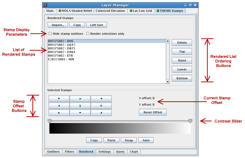
Stamp Layer Functions
- The functions of the Stamp Layer can be accessed by clicking on the Stamp Layer tab in the Layer Manager, which provides access to the following four function tabs.
- 1. Outlines Tab
- Once a search has been completed, the information associated with each stamp appears in a table in the Outlines Tab. Clicking on an entry in this table will highlight the associated stamp in the Viewing Window and vice versa. To find a specific stamp, users can click on the "Find Stamp" button and enter the image id of the stamp they are looking for. Users can also highlight entries and copy them to other programs or send the entire table to a tab delimited text file by clicking on the "Dump Table to File" button.

- 2. Rendered Tab
- The Rendered Tab controls the display of the rendered stamps in the Viewing Window.
- Image Display Preferences: Using the checkboxes at the top-left, users can hide the stamp outline of rendered images and set the stamp layer to only display the rendered stamps that have been elected (highlighted) in the given list.
- Image Ordering: The rendered stamps in the Viewing Window are stacked on top of each other, much like the layers are stacked on each other. The ordering tools can be used to raise or lower images with respect to others, unrender images using the "Delete" button or list the images in left-to-right order using the left-sort button.
- Stamp Offsets: When the rendered stamps in the Viewing Window do not match up perfectly users can shift them using the offset buttons. The arrow buttons indicate the direction of the offset and the center number button indicates the number of pixels per offset (1,2,5 or 10).
- Advanced Options: Using the buttons on the lower-left, users can change the orientation of the stamps (rarely necessary), view the PSD label of the selected image or import/export stamp file lists.
- Image Contrast: The contrast of the rendered images can be adjusted using the slider at the bottom of the page, although this is rarely necessary.
- The Rendered Tab controls the display of the rendered stamps in the Viewing Window.
- 3. Settings Tab
- The Settings Tab controls the display of the stamp outlines in the Viewing Window.
- Stamp Appearance: Users can can change the color of the stamp outline and the stamp fill color using the drop-down boxes at the top. The transparency of the stamp fill color is automatically set to zero, but can be adjusted using the slide bar.
- Layer Name: The name of the Stamp Layer in the Layer Manager is displayed and can be changed by editing the text and hitting "Enter".
- Customize Web Browser: The stamp layer uses a web browser when users right-click on a stamp in the Viewing Window and chose to "Web-Browse" an image. The default web browser is Firefox, but can be changed using this option.
- The Settings Tab controls the display of the stamp outlines in the Viewing Window.

- 4. Query Tab
- The Query Tab is identical to the search screen that appears when opening the Stamp Layer and is used to change the search parameters for additional image searches.
- The Query Tab is identical to the search screen that appears when opening the Stamp Layer and is used to change the search parameters for additional image searches.
Related Pages
-
- Tutorial #1: Viewing THEMIS VIS Coverage
- Tutorial #3: Finding THEMIS Observation Opportunities
- THEMIS Database